EasyManua.ls Logo

Sony Walkman MZ-RH1 User Manual

Sony Walkman MZ-RH1
66 pages
To Next Page IconTo Next Page
Page #1 background imageLoading...
Page #1 background image
SERVICE MANUAL
PORTABLE MD RECORDER
MZ-RH1
Ver. 1.1 2006.05
9-887-182-02
2006E05-1
© 2006.05
Sony Corporation
Personal Audio Division
Published by Sony Techno Create Corporation
Model Name Using Similar Mechanism NEW
MD Mechanism Type MT-MZRH1-181
Optical Pick-up Name ABX-U2
US Model
Canadian Model
AEP Model
SPECIFICATIONS
– Continued on next page –
Audio playing system
MiniDisc digital audio system
Systems
MiniDisc system, Hi-MD system
Laser diode properties
Emission duration: continuous
Laser output: less than 44.6 µW
(This output is the value measured at a distance of
200 mm from the lens surface on the optical pick-up
block with 7 mm a
p
erture.
)
US and foreign patents licensed from Dolby Laboratories.
SonicStage is a trademark or registered trademark of Sony Corporation.
MD Simple Burner, OpenMG, “MagicGate”, “MagicGate Memory
Stick”, “Memory Stick”, Hi-MD, Net MD, ATRAC, ATRAC3,
ATRAC3plus and their logos are trademarks of Sony Corporation.
Microsoft, Windows, Windows NT and Windows Media are trademarks
or registered trademarks of Microsoft Corporation in the United States
and /or other countries.
IBM and PC/AT are registered trademarks of International Business
Machines Corporation.
Macintosh is a trademark of Apple Computer, Inc.
Pentium is a trademark or registered trademark of Intel Corporation.
MPEG Layer-3 audio coding technologyand patents licensed from
Fraunhofer IIS and Thomson.
All other trademarks and registered trademarks are trademarks or
registered trademarks of their respective holders.
™ and ® marks are omitted in this manual.
CD and music-related data from Gracenote, Inc., copyright ˝ 2000-2004
Gracenote. Gracenote CDDB® Client Software, copyright 2000-2004
Gracenote. This product and service may practice one or more of the
following U.S. Patents: #5,987,525; #6,061,680; #6,154,773,
#6,161,132, #6,230,192, #6,230,207, #6,240,459, #6,330,593, and other
patents issued or pending. Services supplied and/or device manufactured
under license for following Open Globe, Inc. United States Patent
6,304,523.
Gracenote is a registered trademarks of Gracenote. The Gracenote logo
and logotype, and the “Powered by Gracenote” logo are trademarks of
Gracenote.
Program © 2001, 2002, 2003, 2004, 2005 Sony Corporation
Documentation © 2006 Sony Corporation
Question and Answer IconNeed help?

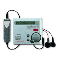
Do you have a question about the Sony Walkman MZ-RH1 and is the answer not in the manual?

Sony Walkman MZ-RH1 Specifications

General IconGeneral
BrandSony
ModelWalkman MZ-RH1
CategoryCD Player
LanguageEnglish

Summary

Recording and Playback Times

Servicing Notes and Precautions

Component Replacement and Repair Guidelines

Notes on chip component replacement, flexible circuit board repair, and specific IC replacements.

Safety Cautions for Servicing

Warning about hazardous radiation exposure from improper adjustments and critical safety components.

Servicing Procedures and System Requirements

Handling Optical Components and Solder

Guidelines for handling optical pick-ups, laser diodes, and using unleaded solder.

Operation Checks and Software Requirements

Procedures for operation checks and system requirements for associated software.

Disassembly Procedures Overview

Disassembly Flow and Lower Panel Removal

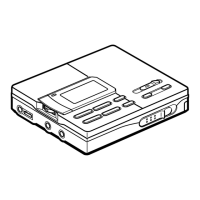
Outlines the disassembly sequence and details removing the lower panel section.

Unit Section Disassembly Steps

Cabinet (Front) and Main Board Removal

Instructions for removing the front cabinet section and the main board.

Major Assembly Disassembly Steps

Upper Panel and Mechanism Deck Removal

Details the procedure for removing the upper panel assembly and the mechanism deck.

Component Disassembly and Installation

Motor and Optical Pick-up Assembly Disassembly

Test Mode Operations Guide

Entering and Navigating Test Mode

Explains how to enter the test mode and navigate between different test modes like Display Check.

Test Mode Configuration Flow

Details the flow for configuring various test modes from the Display Check mode.

Test Mode Functionality Details

Manual Mode Procedures

Guides on using Manual Mode for adjustments, including item switching and value variation.

Specific Test Mode Operations

Overall Adjustment Mode Operation

Procedure for entering and operating the Overall Adjustment mode.

Self-Diagnosis Result Display Mode

How to check the self-diagnosis history to analyze faults.

Test Mode Error Codes and Checks

Self-Diagnosis Error Code Reference

Lists error display codes and their corresponding descriptions for fault analysis.

Clearing Total Recording Time and Key Check

Procedures for clearing total recording time and using the Key Check mode.

Electrical Adjustments and Precautions

Precautions for Electrical Adjustments

Essential precautions and tools required for performing electrical adjustments.

Adjustment Sequence and Initialization

The order of adjustment steps and how to initialize adjustment values.

Power Supply Voltage Adjustments (PwrAdj)

Detailed procedure for adjusting power supply voltages, including PwrAdj specifications.

Electrical Adjustment Procedures

Power Supply Voltage Adjustments (VBsAdj)

Procedure for VBsAdj adjustments, specifying item numbers and test points.

VBsAdj Adjustment Specifications

Table of specifications for VBsAdj adjustments, including measuring points.

Electrical Adjustment and Check Procedures

Charge Function and Laser Power Checks

Procedures for checking the charge function and measuring laser power.

Setting Adjustment Values

Hi-MD3 Setting Procedures

Steps for setting Hi-MD3 adjustment values using calculation formulas.

Destination Setting Procedure

Procedure for setting the destination parameter, e.g., US, Canadian, or AEP models.

Servo Adjustment and Clearing Procedures

Servo Overall Adjustment Operation

Detailed steps for performing servo overall adjustment using specific discs.

Resume Clear and Test Mode Exit

Procedures for clearing adjustments and exiting test mode safely.

Diagrams and Schematics

Block Diagrams of Functional Sections

Block Diagrams of System Sections

Main Board Schematic Diagrams (1/7)

Main Board Schematic Diagrams (2/7)

Main Board Schematic Diagrams (3/7)

Main Board Schematic Diagrams (4/7)

Main Board Schematic Diagrams (5/7)

Main Board Schematic Diagrams (6/7)

Main Board Schematic Diagrams (7/7)

IC Pin Function Descriptions

IC Pin Function Descriptions (Continued - IC801 P1)

IC Pin Function Descriptions (Continued - IC801 P2)

IC Pin Function Descriptions (Continued - IC801 P3)

IC Pin Function Descriptions (Continued - IC801 P4)

IC Pin Function Descriptions (Continued - IC801 P5)

IC Pin Function Descriptions (Continued - IC801 P6)

OLED Board IC Pinout Description

Exploded Views Overview

Exploded Views of Unit Sections

Exploded Views of Lower Panel and Chassis

Exploded Views of Set Chassis and Main Board

Exploded Views of Main Board and Mechanism Deck

Mechanism Deck Section Exploded View

Related product manuals