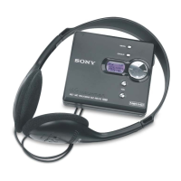
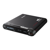
MZ-RH1
7
3-3. CABINET (FRONT) SECTION
3-4. MAIN BOARD
5
Remove the cabinet (front)
section in the direction of
arrow
B
.
2
flexible board
(18core) (CN471)
panel (upper) assy
A
B
3
screw (M1.4)
4
Remove from the convex
part of the screw hole.
convex part of screw hole
1
Push the knob (open) in the direction
of arrow
A
and open the panel (upper)
section.
convex part of screw hole
4
Remove from the convex part of the screw hole.
The screw fixing areas
is cleaned.
3
Remove two solders of the
flexible board (over write head
(HR601)).
4
OP flexible boar
(CN501)
2
shield assy
7
MAIN board
1
three screws (M1.4)
6
two screws (M1.4)
5
motor flexible
board (CN701)
Note: When mounting the MAIN Board, clean
the screw fixing areas (5 places
×
both
sides) of the MAIN Board with alcohol
(ethanol), and then tighten the screws.
Also, when tightening the screws, use
a torque driver and tighten them to a
torque range of 0.06 – 0.08N.
(Excessive torque over 0.1N could
bend the chassis.)
(Without cleaning, or with the screws
tightened loosely, the set may not start
when the USB cable is inserted.)
Ver. 1.1
 Loading...