MZ-RH1
6
Note: Follow the disassembly procedure in the numerical order given.
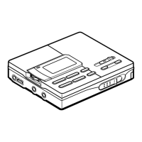
3-2. PANEL (LOWER) SECTION
• This set can be disassembled in the order shown below.
3-1. DISASSEMBLY FLOW
SECTION 3
DISASSEMBLY
6
panel (lower) section
S464
knob (hold)
2
two bosse
1
Open the
battery case lid.
3
battery case lid
4
screw
(M1.4)
5
two screws
(M1.4)
Note: On installation of panel (lower)
section, adjust the position of
switch (S464) and knob (hold).
5
two screws
(M1.4)
knob (hold)
S464
3-2. PANEL (LOWER) SECTION
(Page 6)
3-6. MECHANISM DECK
(MT-MZRH1-181)
(Page 8)
3-3. CABINET (FRONT) SECTION
(Page 7)
3-4. MAIN BOARD
(Page 7)
3-5. PANEL (UPPER) ASSY
(Page 8)
SET
3-7. TORSION SPRING (POP UP L),
TORSION SPRING (POP UP R)
(Page 9)
3-8. GEAR (SA), GEAR (SB)
(Page 9)
3-12. POSITION OF FERRITE CORE
(Page 11)
3-9. OP SERVICE ASSY (ABX-U2)
(Page 10)
3-10. DC MOTOR SSM18D/C-NP (SPINDLE) (M701),
DC MOTOR (SLED) (M702),
DC MOTOR UNIT (OVER WRITE HEAD UP/DOWN) (M703)
(Page 10)
3-11. HOLDER ASSY
(Page 11)
 Loading...