Do you have a question about the Sony PCM-R500 and is the answer not in the manual?
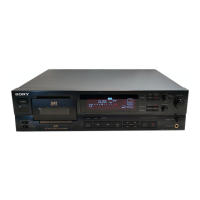
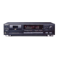
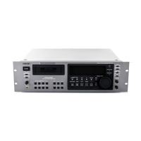
| Type | DAT (Digital Audio Tape) Recorder |
|---|---|
| Tape Speed | 8.15 mm/s |
| Recording Time | Up to 120 minutes (with 120-minute tape) |
| Sampling Frequency | 48 kHz, 44.1 kHz, 32 kHz |
| Frequency Response | 20Hz to 20kHz ±0.5dB |
| Signal to Noise Ratio | 90 dB |
| Digital Inputs | Coaxial (RCA), Optical (Toslink) |
| Digital Outputs | Coaxial (RCA), Optical (Toslink) |
| Analog Inputs | RCA |
| Analog Outputs | RCA |
| Power Supply | AC 120V, 60Hz |
| Total Harmonic Distortion | 0.005% |
Details of analog and digital input connection types and levels.
Analog and digital output connector types, levels, and impedances.
Procedures for checking AC leakage from exposed metal parts.
Guide to connecting the deck to audio components and amplifiers.
Common issues and their solutions for deck operation.
How to enter and utilize the deck's test modes for adjustments.
Procedures for mechanical alignments and tape path adjustments.
Steps for electrical calibrations, including sensor and signal adjustments.
Guide for checking and replacing the clock backup battery.
Overview of the unit's functional blocks, particularly the power section.
Component layout for the RF section's printed wiring boards.
Circuit schematic for the RF section of the device.
Component layout for the MD section's printed wiring boards.
Component layout for the AUDIO section's printed wiring boards.
Component layout for the DISPLAY section's printed wiring boards.
Detailed pinout and function for various ICs used in the unit.