Do you have a question about the Sony MDS-JA50ES and is the answer not in the manual?
Details laser properties, output, and disc type compatibility.
Provides frequency response, S/N ratio, and wow/flutter details.
Details connector types, impedance, and signal levels for inputs/outputs.
Procedures for checking AC leakage from metal parts to ground.
Highlights critical components marked with A for safe operation.
Describes methods for performing a forced system reset.
Outlines steps to enter and use the retry cause display mode.
Explains the meaning of various signs displayed on the tube.
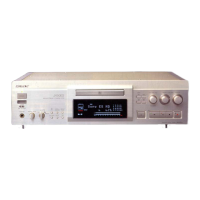
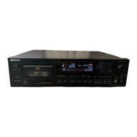
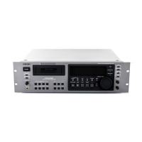
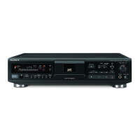
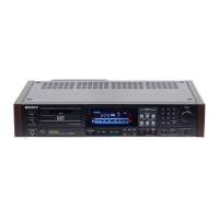
Identifies and describes the location and function of all controls and indicators.
Explains how to set the internal clock for date and time stamping.
Guides on how to play back an MD disc.
Step-by-step guide on how to record audio onto an MD.
Details how track numbers are marked based on recording source and settings.
Steps for adjusting the digital recording level.
Explains the No Clip Function for digital recording.
How to use the display to check disc and track information.
Overview of methods to locate specific tracks using controls.
How to erase single tracks or all tracks on an MD.
How to divide existing tracks into multiple parts.
How to change the order of tracks on an MD.
Detailed steps for disassembling the tray assembly.
Guidance on precautions to take when reassembling parts.
Instructions on how to enter the test mode.
Lists the available test modes selectable via the AMS knob.
Detailed steps for operating the continuous playback test mode.
Safety precautions for checking laser diode emission.
Precautions for handling the optical pick-up to prevent damage.
General precautions and order for performing electrical adjustments.
Step-by-step method for traverse adjustment.
Checking error rates on a CD.
Checking error rates on an MO disc.
Block diagram of the BD section.
Diagrams showing the location of various circuit boards.
Illustrates waveforms for various sections of the unit.
Printed wiring diagram for BD Board Side A.
Printed wiring diagram for the Digital Board Side A.
Printed wiring diagrams for the MD section components.
Schematic diagram for the DIO board.
Schematic diagram for the power supply section.
Block diagram for IC121 (CXD2535CR).
Block diagram for IC206 (ATRAC Encoder/Decoder).
Block diagram for IC501 (Noise Shaper/Digital Filter).
Lists pin functions for IC101 (RF Amplifier).
Details pin functions for IC202 (System Controller).
Exploded view of the main section of the unit.
Exploded view of the chassis section.
Exploded view of the front panel section 1.
Notes regarding parts list differences and ordering.
Lists resistor types and specifications.
List of integrated circuits with part numbers.
List of coils with specifications.
List of motors with part numbers.
Lists hardware components like screws and washers.
List of fuses with specifications.
Lists IC link components.
List of transistors with specifications.
| Type | MiniDisc Deck |
|---|---|
| Recording System | ATRAC (Adaptive TRansform Acoustic Coding) |
| Sampling Frequency | 44.1 kHz |
| Dynamic Range | 98 dB |
| Analog Inputs | RCA |
| Remote Control | Yes |
| Frequency Response | 20 Hz - 20 kHz |
| Digital Inputs | Coaxial, Optical |
| Digital Outputs | Coaxial, Optical |
| Analog Outputs | RCA |
| Wow and Flutter | Unmeasurable |