Do you have a question about the Sony Play Station 2 and is the answer not in the manual?
Details copyright, distribution policy, and manual revision status.
Covers risks like laser eye hazard, electric shock, and overheating.
Information on lithium battery handling and environmental regulations.
Guidelines to prevent static discharge damage during servicing.
Identification of model labels and void tape.
Procedure for installing the main lid assembly.
Procedure for attaching cover screws and fitting caps.
Installation of the upper cover and switch block assembly.
Assembly of buttons, switches, and mounting brackets.
Procedure for connecting the front terminal board.
Steps for replacing the lower cover assembly.
Installation of the power block and related harness.
Installation of the Shield HDD component.
Fitting insulating sheets and barrier labels.
Installation of the power switch with AC inlet.
Installation of the DC fan and rear panel.
Securing Shield B using specific screws and tapping.
Placement of heat sink insulating sheets on IC components.
Connecting flat cables and harnesses to the main board.
Installation of GH010 mounting brackets.
Placement of heat-resistant sheet on Shield A assembly.
Installation of Shield A assembly and MD Block.
Procedure for replacing the CR2032 lithium battery.
Changing pulley bracket and applying caution/laser labels.
Procedure for installing the pulley and bracket assembly.
Installation of the tray assembly and ornamental plate.
Securing the optical device (KHS-400B) with retaining screws.
Details on servicing and adjusting the optical device.
Installation of cam retainer screws and tilt mechanisms.
Attaching the DC motor using tapping screws.
Installation of guide components and main plates.
Installation of the sub chassis assembly.
Attaching the spindle motor and main plates.
Fitting the tilt spring (leaf) component.
Securing components with step screws.
Installation of insulators and the main chassis assembly.
Assembly of the sub frame and main frame.
Installation of rubber belts and gears.
Installation of cam slide, pulley, and driving gear.
Installation of the loading DC motor and switch leaf.
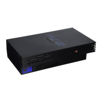
| Manufacturer | Sony Computer Entertainment |
|---|---|
| Type | Home video game console |
| Generation | Sixth generation |
| Discontinued | January 4, 2013 |
| CPU | Emotion Engine |
| CPU Speed | 294.912 MHz |
| GPU | Graphics Synthesizer |
| Graphics Clock Speed | 147.456 MHz |
| RAM | 32 MB RDRAM |
| Optical Drive | DVD-ROM |
| Best-Selling Game | Grand Theft Auto: San Andreas |
| Units Sold | Over 155 million |
| Release Date | March 4, 2000 |
| Media | DVD, CD |
| Video Output | Composite video, S-Video, RGB, Component video |
| Storage | Memory card |
| Resolution | 480i, 480p, 576i, 1080i |
| Audio | Stereo |
| Connectivity | Ethernet |
| Controller Input | DualShock 2 |
| Dimensions | 301 mm x 78 mm x 182 mm |
| Weight | 2.2 kg |
| Backward Compatibility | PlayStation |