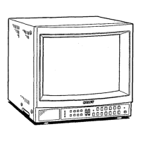
>VM-1341/13420/1343MD
SECTION 3
SET-UP ADJUSTMENTS
• The following adjustments should be made when
a complete realignment is required or a new picture
tube is installed.
• These adjustments should be performed with rated
power supply voltage unless ontherwise noted.
The control and switch below shoul~ be set as follows
unless otherwise noted :
CONTRAST control ········· 80%
BRIGHTNESS control ······· 50%
Precaution
• Set the side of the unit with the PICTURE TUBE
so that it faces east or west in· oder to reduce
the influence of external magnetic force.
• Turn the power switch for the unit ON and erase
the magnetic force using a degausser.
[ 3-1 . BEAM LANDING [
1. Receive an entirely white signal with the pattern
generator.
CONTRAST ········· MAX.
BRIGHTNESS ······· set easy to observe
2. Adjust the focus and the horizontal convengence
roughly.
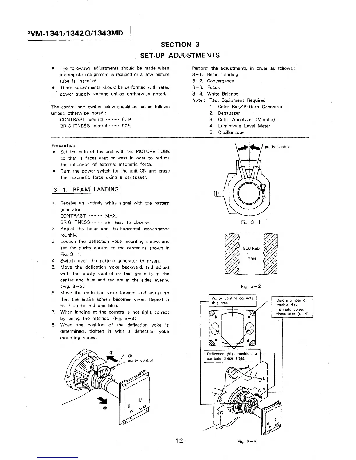
3. Loosen the deflection yoke mounting screw, and
set the purity control to the center as shown in
Fig. 3-1.
4. Switch over the pattern generator to green.
5. Move the deflection yoke backward, and adjust
with the purity control so that green is in the
center and blue and red are at the sides, evenly.
(Fig. 3-2)
6. Move the deflection yoke forward, and adjust so
that the entire screen becomes green. Repeat 5
to 7 as to red and blue.
7. When landing at the corners is not right, correct
by using the magnet. (Fig. 3- 3)
8. When the position of the deflection yoke is
determined, tighten it with a deflection yoke
mounting screw.
@
-12-
Perform the adjustments in order as follows :
3-1. Beam Landing
3 - 2. Convergence
3-3. Focus
3-4. White Balance
Note: Test Equipment Required.
1. Color Bar /Pattern Generator
2. Degausser
3. Color Annalyzer (Minolta)
4. Luminance Level Meter
5. Oscilloscope
purity control
Fig. 3-1
Fig. 3-2
control corrects
Fig. 3-3
Disk magnets or
rotable disk
magnets correct
these area (a-d).