Screen-corner Convergence
b
C
a-d :screen-corner
misconver ence
a
d
@ Affix a permalloy ass'y
I
'®
3-3. FOCUS
I. Receive the broadcast.
I
corresponding to the
misconverged areas.
/ (The rearside of picture tube)
2. CONTRAST - Norma'!
3. Adjust FOCUS control so that the focus on the center of screen
becomes to the best.
FBT
3-4. WHITE BALANCE
[Screen (G2) Voltage Adjustment]
FOCUS
I. Receive a dot signal with the pattern generator.
2. Adjust
R. G. B cut-off controls so that respective cathode voltage
against ground becomes I03V DC.
3. Observing the screen, adjust SCREEN control so that the back-
ground of the dot signal is bright dimly.
FBT
SCREEN
[White Balance]
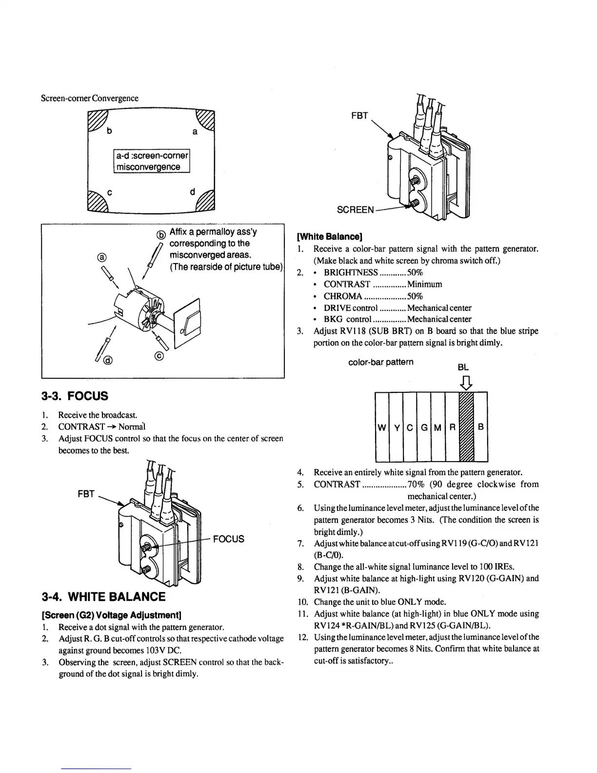
1. Receive a color-bar pattern signal with the pattern generator.
(Make black and white screen by chroma switch off.)
2. • BRIGHTNESS ............ 50%
• CONTRAST ............... Minimum
• CHROMA ................... 50%
• DRIVE control ............ Mechanical center
• B KG control.. ............. Mechanical center
3.
Adjust RV! 18 (SUB BRT) on B board so that the blue stripe
portion on the color-bar pattern signal is bright dimly.
color-bar pattern
BL
W Y C G M R
B
4. Receive an entirely white signal from the pattern generator.
5. CONTRAST .................... 70 % (90 degree clockwise from
mechanical center.)
6. Using the luminance level meter, adjust the luminance level of the
pattern generator becomes 3 Nits. (The condition the screen is
bright dimly.)
7. Adjust white balanceatcut-offusingRVl 19 (G-C/O) andRV121
(B-C/0).
8. Change the all-white signal luminance level to 100 IREs.
9. Adjust white balance at high-light using RV120 (G-GAIN) and
RV121 (B-GAIN).
JO. Change the unit to blue ONLY mode.
11. Adjust white balance (at high-light) in blue ONLY mode using
RV124 *R-GAIN/BL) and RV125 (G-GAIN/BL) .
12. Using the luminance level meter, adjust the luminance level of the
pattern generator becomes 8 Nits. Confirm that white balance at
cut-off is satisfactory ..
 Loading...