• PIN PHASE (RV504)
[ITI}{[JJJ+[[]]
• V. ANG (RV550)
• BOW (RV509)
6. Adjust RV503 CH. SIZE) so that the horizontal
size becomes 15. 75 ± 0.2 frames.
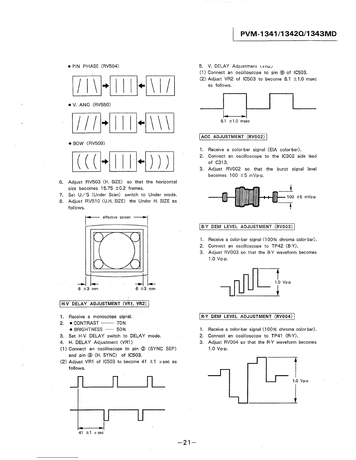
7. Set U/S (Under Scan) switch to Under mode.
8. Adjust RV510 (U.H. SIZE) the Under H. SIZE as
follows.
_J
6 ±3 mm
6 ±3 mm
I H-V DELAY ADJUSTMENT (VR1, VR2) I
1. Receive a monoscbpe signal.
2. • CONTRAST ········· 70%
• BRIGHTNESS ······ 50%
3. Set H-V DELAY switch to DELAY mode.
4. H. DELAY Adjustment (VR1)
(1) Connect an oscilloscope to pin @ (SYNC SEP)
and pin ® (H. SYNC) of IC503.
(2) Adjust VR1 of IC503 to become 41 ± 1 µ sec as
follows.
41 ±1 µsec
-21-
PVM-1341 /13420/1343MD
5. V. DELAY AdJustmem 1. v n.::.;
(1) Connect an oscilloscope to pin ® of IC503.
(2) Adjust VR2 of IC503 to become 8.1 ± 1.0 msec
as follows.
8.1 ±1.0 msec
I ACC ADJUSTMENT (RV002) I
1. Receive a color-bar signal (EIA color-bar).
2. Connect an oscilloscope to the IC302 side lead
of C313.
3. Adjust RV002 so that the burst signal level
becomes 100 ±5 mVp-p.
100 ±5 mVp-p
I B-Y DEM LEVEL ADJUSTMENT (RV003) I
1. Receive a color-bar signal (100% chroma color-bar).
2. Connect an oscilloscope to TP42 (B-Y).
3. Adjust RV003 so that the B-Y waveform becomes
1.0 Vp-p.
t
1.0 Vp-p
i
j R-Y DEM LEVEL ADJUSTMENT (RV004) I
1. Receive a color-bar signal (100% chroma color-bar).
2. Connect an oscilloscope to TP41 (R-Y).
3. Adjust RV004 so that the R-Y waveform becomes
1.0 Vp-p.
-=i
1.0 Vp-p
l