PVM-1341 /13420/1343MD
f MATRIX ADJUSTMENT (RV006, RV007) j
1. Receive a color-bar signal.
(
white peak : 75. % )
black level : 0%
chroma max. : 75%
chroma min. : 0%
2. CONTRAST ············ 70%
3. Connect an oscilloscope to pin @ (B OUT) of
A-15.
4. Adjust RV006 (8-Y) so that the BLUE OUT wave-
form becomes flat as following figure.
Blue OUT
magenta
+
__i within
0.2 Vp-p
5. When there is difference between cyan portion and
magenta portion, adjust with RV006 while tracking
with PHASE volume for user control.
6. Connect an oscilloscope to pin @ (R-Y) of A-15.
7. Adjust RV007 (R-Y) so that the RED OUT wave-
form becomes flat as following figure.
-22-
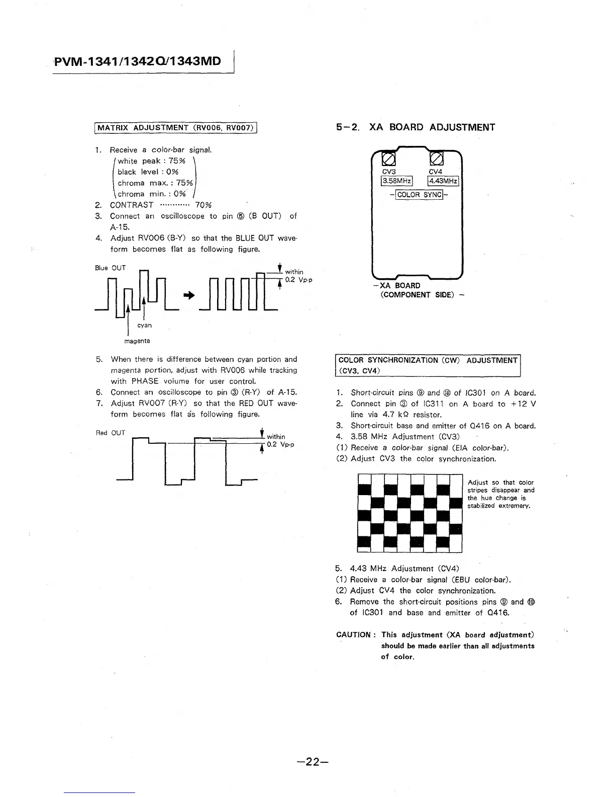
5-2. XA BOARD ADJUSTMENT
CVS CV4
I 3.58MHz \ \.-4.-43-M-H-,z \
-\COLOR SYNC\-
-XA BOARD
(COMPONENT SIDE)
COLOR SYNCHRONIZATION (CW) ADJUSTMENT
(CV3, CV4)
1. Short-circuit pins ® and @) of IC301 on A board.
2. Connect pin @ of IC311 on A board to + 12 V
line via 4.7 kQ resistor.
3. Short-circuit base and emitter of 0416 on A board.
4. 3.58 MHz Adjustment (CV3)
(1) Receive a color-bar signal (EIA color-bar).
(2) Adjust CV3 the color synchronization.
5. 4.43 MHz Adjustment (CV4)
Adjust so that color
stripes disappear and
the hue change is
stabilized extremery.
(1) Receive a color-bar signal (EBU color-bar).
(2) Adjust CV4 the color synchronization.
6. Remove the short-circuit positions pins ® and @)
of IC301 and base and emitter of Q416.
CAUTION : This adjustment (XA board adjustment)
should be made earlier than all adjustments
of color.