PVM-1341 /1342Q/1343MD
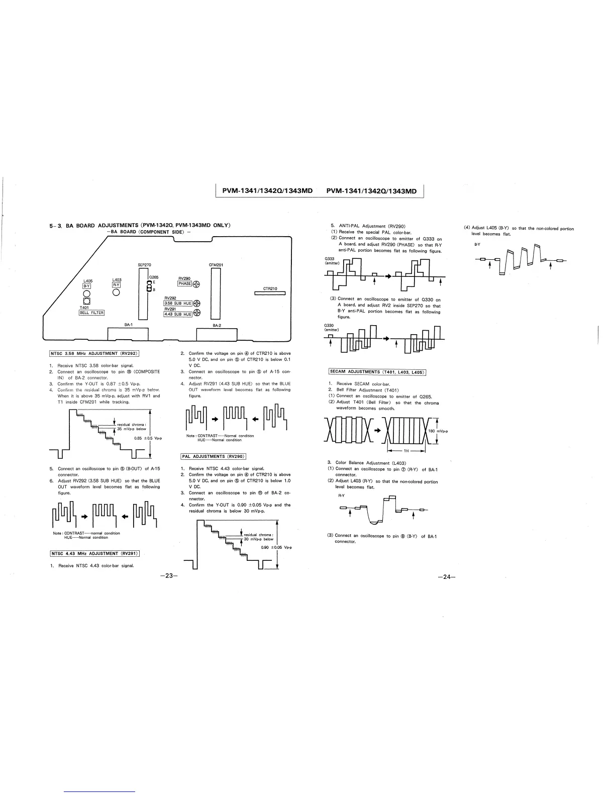
5-3. BA BOARD ADJUSTMENTS (PVM-1342O. PVM-1343MD ONLY)
-BA BOARD (COMPONENT SIDE) -
SEP270
L403
0265
L405
§:
jB-Yj
IR-Yj
0
0
D
T401
I BELL FILTER I
BA-1
j NTSC 3.58 MHz ADJUSTMENT (RV292) I
1. Receive NTSC 3.58 color-bar signal.
2. Connect an oscilloscope to pin @ (COMPOSITE
IN) of BA-2 connector.
3. Confirm the Y-OUT is 0.87 ± 0.5 Vp-p.
4. Confirm the residual chroma is 35 mVp-p below.
When it is above 35 mVp-p, adjust with RV1 and
T1 inside CFM201 while tracking.
5. Connect an oscilloscope to pin @ (B-OUD of A-15
connector.
6. Adjust RV292 (3.58 SUB HUE) so that the BLUE
OUT waveform level becomes flat as following
figure.
Note: CONTRAST······normal condition
HUE··--··Normal condition
j NTSC 4.43 MHz ADJUSTMENT (RV291) I
1. Receive NTSC 4.43 color-bar signal.
CFM201
RV290
jPHASEI@
CTR210
RV292
j3.58 SUB HUEI@
RV291 EIB
j4.43 SUB HUEI
~
-23-
BA-2
2. Confirm the voltage on pin@ of CTR210 is above
5.0 V DC, and on pin @ of CTR210 is below 0.1
V DC.
3. Connect an oscilloscope to pin @ of A-15 con-
nector.
4. Adjust RV291 (4.43 SUB HUE) so that the BLUE
OUT waveform level becomes flat as following
figure.
Note: CONTRAST······Normal condition
HUE··--··Normal condition
j PAL ADJUSTMENTS (RV290) I
1. Receive NTSC 4.43 color-bar signal.
2. Confirm the voltage on pin@ of CTR210 is above
5.0 V DC, and on pin @ of CTR210 is below 1.0
V DC.
3. Connect an oscilloscope to pin ® of BA-2 co-
nnector.
4. Confirm the Y-OUT is 0.90 ±0.05 Vp-p and the
residual chroma is below 30 mVp-p.
0.90 ±0.05 Vp-p
=l
PVM-1341 /13420/1343MD
5. ANTI-PAL Adjustment (RV290)
( 1) Receive the special PAL color-bar.
(2) Connect an oscilloscope to emitter of 0333 on
A board, and adjust RV290 (PHASE) so that R-Y
anti-PAL portion becomes flat as following figure.
Q333
(emitter)
(3) Connect an oscilloscope to emitter of 0330 on
A board, and adjust RV2 inside SEP270 so that
B-Y anti-PAL portion becomes flat as following
figure.
+ +
I SECAM ADJUSTMENTS (T401, L403, L405) J
1. Receive SECAM color-bar.
2. Bell Filter Adjustment (T 401)
(1) Connect an oscilloscope to emitter of 0265.
(2) Adjust T401 (Bell Filter) so that the chroma
waveform becomes smooth.
+
3. Color Balance Adjustment (L403)
(1) Connect an oscilloscope to pin (J) (R-Y) of BA-1
connector.
(2) Adjust L403 (R-Y) so that the non-colored portion
level becomes flat.
(3) Connect an oscilloscope to pin @ (B-Y) of BA-1
connector.
-24-
(4) Adjust L405 (B-Y) so that the non-colored portion
level becomes flat.
B-Y