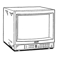
>VM-1341 /13420/1343MD
TABLE OF CONTENTS
1. GENERAL
1-1. Features······ ······················································5
1-2. Location and Function of Parts and Controls···6
2. DISASSEMBLY
2-1. Rear Cover and Top Cover Removal ·················9
2-2. Terminal Board Remova1····································9
2-3. Bracket of Terminal Board Removal ................ 1 0
2-4. Control Unit Removal .. : ................................... 10
2-5. Picture Tube Removal ..................................... 11
3. SET-UP ADJUSTMENTS
3-1. Beam Landing ................................................ · 12
3-2. Convergence .................................................... 13
3-3. Focus· .... ············ .. · ... ··· ......... ········· .... · .. ·· ........ · 14
3-4. White Balance ...... · .. · · · · · ···· ···· · .. ·· · .. · · ..... · .. · ·· .. · ... 15
4. SAFETY RELATED ADJUSTMENTS .. ··················· 17
5. CIRCUIT ADJUSTMENTS
5-1. A Board Adjustments····'································· 19
5-2. XA Board Adjustment ..................................... 22
5-3. BA Board Adjustments ·
(PVM-1342O, 1343MD ONLY) ························23
6. DIAGRAMS
6-1. Frame Schematic Diagram ·······························25
6-2. Block Diagrams·············· .................................. 23
6-3. Printed Wiring Boards ..................................... 36
6-4. Circuit Boards Location ................................... 41
6-5. Schematic Diagram .......................................... 41
6-6. Semiconductors····································· .. ·········62
7. EXPLODED VIEWS
7-1. Chassis ............................................................ 65
7-2. Picture Tube ................................................... 66
8. ELECTRICAL PARTS LIST .................................... 67
WARNING!!
AN ISOLATION TRANSFORMER SHOULD BE USED
DURING ANY SERVICE TO AVOID POSSIBLE SHOCK
HAZARD, BECAUSE OF LIVE CHASSIS.
THE CHASSIS OF THIS RECEIVER IS DIRECTLY CON.
NECTED TO THE AC POWER LINE.
SAFETY.RELATED COMPONENT WARNING!!
COMPONENTS IDENTIFIED BY SHADING AND MARK
L'.h ON THE SCHEMATIC DIAGRAMS. EXPLODED
VIEWS AND IN THE PARTS LIST ARE CRITICAL TO
SAFE OPERATION. REPLACE THESE COMPONENTS
WITH SONY PARTS WHOSE PART NUMBERS APPEAR
AS SHOWN IN THIS MANUAL OR IN SUPPLEMENTS
PUBLISHED BY SONY. CIRCUIT ADJUSTMENTS
THAT ARE CRITICAL TO SAFE OPERATION ARE
IDENTIFIED IN THIS MANUAL. FOLLOW THESE PRO:
CEDURES WHENEVER CRITICAL COMPONENTS ARE
REPLACED OR IMPROPER OPERATION IS SUSPECTED.
PVM-1343MD ONLY
-4-
Notes on Leakage
Current Measurement
This measurement should be done only by B.E.D.
(Biomedical Engineering Department) technician in a
hospital.
Leakage current of this model should be measured in
accordance with UL 544, Item 27.
Important points in leakage current measurement are given
below.
For further information, refer to UL 544 of UL standards.
• This model is for patient care equipment which
corresponds to UL 544.
• For measurement, use the SA 1116 input circuit described
in paragraph 27.5 of UL 544.
• The measurement procedure is described in paragraphs
27.5-27.13 of UL 544.
• When leakage current is measured, the waveform of the
current must be sinusoidal and must not contain high
frequency components (above 1 kHz).
In order to check this, connect an oscilloscope to both
ends of the input circuit connected to the equipment, and
observe the waveform.
A) If high frequency components (above 1 kHz) of a clear
level are found, refer to paragraph 27.5 of UL 544.
B) If high frequency components (above 1 kHz) of an
unclear level are found, pull out the F·5 connector on the
F printed wiring board.
ATTENTION!!
AFIN D'EVITER TOUT RISQUE D'ELECTROCUTl<JN
PROVENANT D'UN CHASSIS SOUS TENSION, UN
TRANSFORMATEUR D'ISOLEMENT DOIT ETRE
UTILISE LORS DE TOUT DEPANNAGE.
LE CHASSIS DE CE RECEPTEUR EST DIRECTEMENT
RACCORDE A L'ALIMENTATION SECTEUR.
ATTENTION AUX COMPOSANTS RELATIFS A LA
SECURITE!!
LES COMPOSANTS IDENTIFIES PAR UNE TRAME ET
PAR UNE MARQUE &suR LES SCHEMAS DE PRINCIPE,
LES VUES EXPLOSEES ET LES LISTES DE PIECES
SONT D'UNE IMPORTANCE CRITIQUE POUR LA
SECURITE DU FONCTIONNEMENT. NE LES REM-
PLACER QUE PAR DES COMPOSANTS SONY DONT LE
NUMERO DE PIECE EST INDIQUE DANS LE PRESENT
MANUEL OU DANS DES SUPPLEMENTS PUBLIES PAR
SONY. LES REGLAGES DE CIRCUIT DONT L'IMPOR-
TANCE EST CRITIQUE POUR LA SECURITE DU
FONCTIONNEMENT SONT IDENTIFIES DANS LE
PRESENT MANUEL. SUIVRE CES PROCEDURES LORS
DE CHAQUE REMPLACEMENT DE COMPOSANTS
CRITIQUES, OU LORSQU'UN MAUVAIS FONCTIONNE-
MENT EST SUSPECTE.
 Loading...