I
-.J
I
PICTURE ADJUSTMENT Buttons
The picture adjusbnent buttons of each monitor operate in the following input mode (indicator as "Yes")
Model Input Mode APERTURE
• LINE A, LINE B
PVM-1343MD/
-vie
Yes
PVM-1342Q/
• Analog RGB
PVM-1341 • Digital RGB
• Analog RGB
No
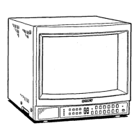
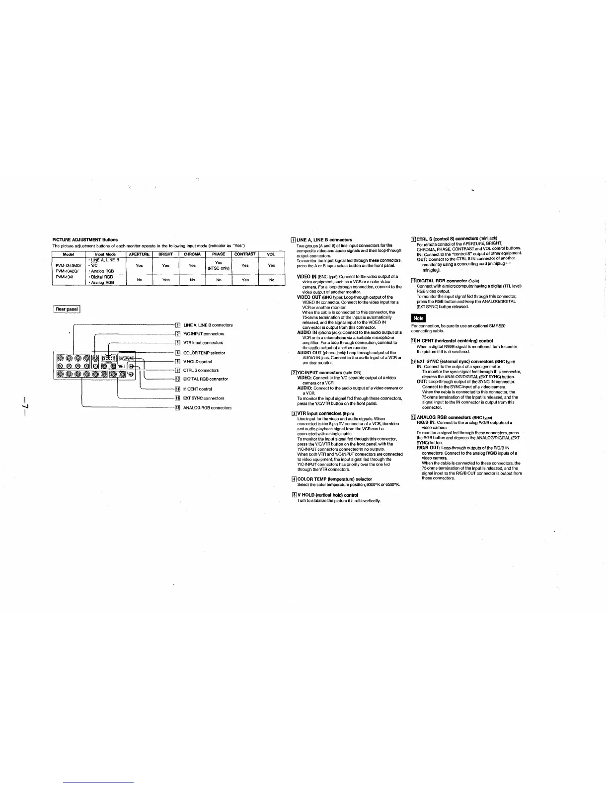
j Rear panel I
BRIGlfT
Yes
Yes
CHROMA PHASE
Yes
Yes
(NTSC only)
No No
LINE A, LINE B connectors
Y/C-INPUT connectors
I ;± [I] VTR Input connectors
I = = = d!§l::: Lr-~~~ I II] COLOR TEMP selector
III
1 ···· m
l=:
V HOLD control
CTRL S connectors
DIGITAL RGB connector
H CENT control
~---------rn] EXT SYNC connectors
~----------------IIlJ ANALOG RGBconnectors
CONTRAST
Yes
Yes
VOL
Yes
No
IJ]LINE A, LINE B connectors
Two groups (A and B) of line input connectors for the
composite video and audio signals and their loop-through
output connectors.
To monitor the input signal led through these connectors,
press the A or B input select button on the front panel.
VIDEO IN (BNC type): Connect to the video output of a
video equipment, such as a VCR or a color video
camera. For a loop-through connection, connect to the
video output of another monitor.
VIDEO OUT (BNC type): Loop-through output of the
VIDEO IN connector. Connect to the video input for a
VCR or another monitor.
When the cable is connected to this connector, the
75-0hms termination of the input is automatically
released, and the signal input to the VIDEO IN
connector is output from this connector.
AUDIO IN (phono jack): Connect to the audio output of a
VCR or to a microphone via a suitable microphone
amplifier. For a loop-through connection, connect to
the audio output of another monitor.
AUDIO OUT (phono jack): Loop-through output of the
AUDIO IN jack. Connect to the audio input of a VCR or
another monitor.
[I]Y/CINPUT connectors (4pin DIN)
VIDEO: Connect to the Y/C separate output of a video
camera or a VCR.
AUDIO: Connect to the audio output of a video camera or
a VCR.
To monitor the Input signal fed through these connectors,
press the Y/CNTR button on the front panel.
[I]VTR input connectors (8-pin)
Line input for the video and audio signals. When
connected to the 8-pin TV connector of a VCR, the video
and audio playback signal from the VCR can be
connected with a single cable.
To monitor the input signal led through this connector,
press the Y/CNTR button on the front panel, with the
Y/C-INPUT connectors connected to no outputs.
When both VTR and Y/C-INPUT connectors are connected
to video equipment, the input signal fed through the
Y/CINPUT connectors has priority over the bne fdd
through the VTR connectors.
IJ]COLOR TEMP (temperature) selector
Select the color temperature position, 9300°K or 6500°1<.
II)V HOLD (vertical hold) control
Turn to stabilize the picture if II rolls v~rtlcally.
G
II] CTRL S (control S) connectors (minijack)
For remote control of the APERTURE, BRIGHT,
CHROMA, PHASE, CONTRAST and VOL control buttons.
IN: Connect to the "control S" output of other equipment.
OUT: Connect to the CTRL S IN connector of another
monitor by using a connecting cord (miniplug-
miniplug).
@DIGITAL RGB connector (9-pin)
Connect with a microcomputer having a digital (TTL level)
RGB video output.
To monitor the input signal fed through this connector,
press the RGB button and keep the ANALOG/DIGITAL
(EXT SYNC) button released.
-
For connection, be sure to use an optional SMF-520
connecting cable.
!Ii] H CENT (horizontal centering) control
When a digital R/G/B signal is monitored, turn to center
the picture if It Is decentered.
[i.21 EXT SYNC (external sync) connectors (BNC type)
IN: Connect to the output of a sync generator.
To monitor the sync signal fed through this connector,
depress the ANALOG/DIGtT AL (EXT SYNC) button.
OUT: Loop-through output of the SYNC IN connector.
Connect to the SYNC input of a video camera.
When the cable Is connected to this connector, the
75-0hms termination of the input is released, and the
signal input to the IN connector is output from this
connector.
IIlJANALOG RGB connectors (BNCtype)
R/G/8 IN: Connect to the analog R/G/8 outputs of a
video camera.
To monitor a signal fed through these connectors, press
the RGB button and depress the ANALOG/DIGIT AL (EXT
SYNC) button.
R/G/B OUT: Loop-through outputs of the R/G/8 IN
connectors. Connect to the analog R/G/8 inputs of a
video camera.
When the cable is connected to these connectors, the
75-0hms termination of the input is released, and the
signal input to the R/G/8 OUT connector is output from
these connectors.
 Loading...