I
Q')
I
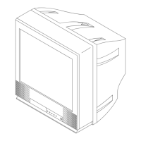
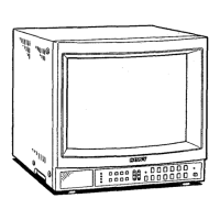
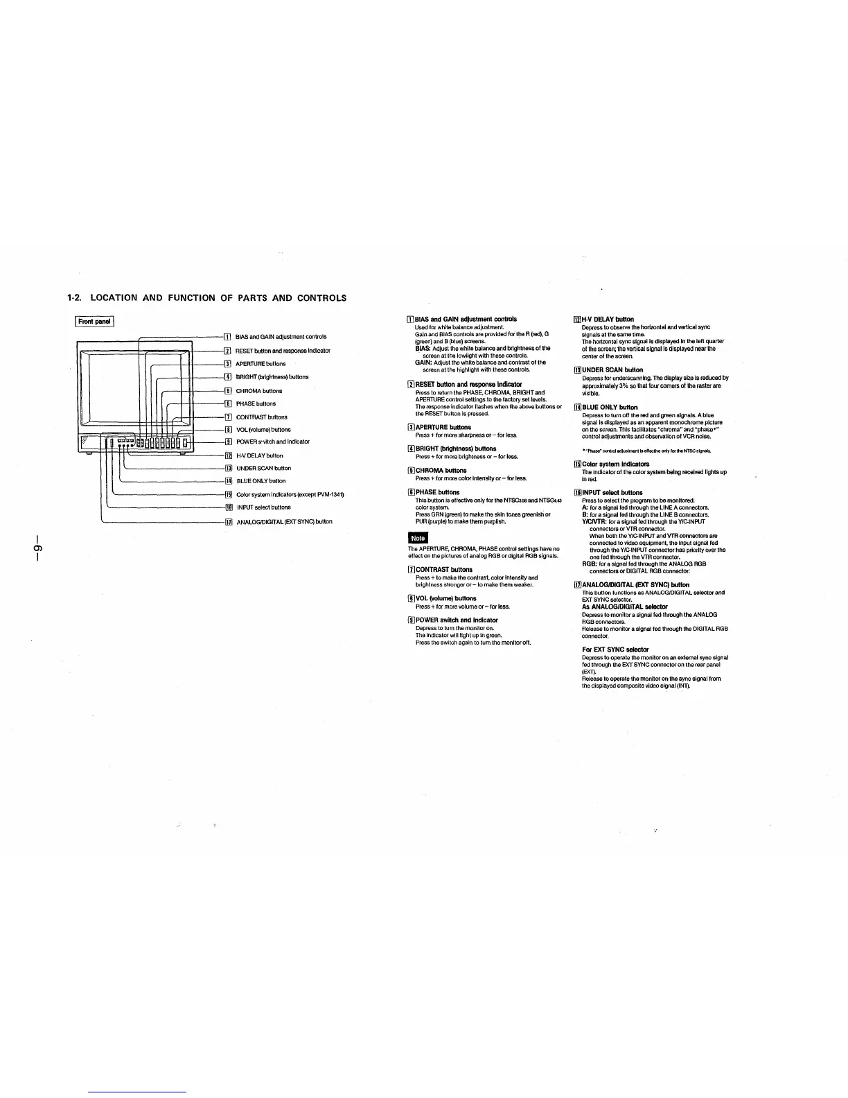
1-2. LOCATION AND FUNCTION OF PARTS AND CONTROLS
I Front panel I
~
W'
• J
181'!I
,. . .,,
.i l
a I
-
l
I
rn
.1,
.!.
J..,
6
7
B
J..,
12
13
.1_4_,
15
16
11
BIAS and GAIN adjustment controls
RESET button and response Indicator
APERTURE buttons
BRIGHT (brightness) buttons
CHROMA buttons
PHASE buttons
CONTRAST buttons
VOL (volume) buttons
POWER s",itch and Indicator
H-V DELAY button
UNDER SCAN button
BLUE ONLY button
Color system indicators (except PVM-1341)
INPUT select buttons
ANALOG/DIGITAL (EXT SYNC) button
[I] BIAS and GAIN adjustmant controls
Used for white balance adjustment.
Gain and BIAS controls are provided tor the R (red), G
(green) and B (blue) screens.
BIAS: Adjust the white balance and brightness of the
· screen at the lowlight with these controls.
GAIN: Adjust the white balance and contrast of the
screen at the highlight with these controls.
[1] RESET button and response Indicator
Press to return the PHASE, CHROMA, BRIGHT and
APERTURE control settings to the factory set levels.
The response Indicator flashes when the above buttons or
the RESET button is pressed.
[l]APERTURE buttons
Press + for more sharpness or - for fess.
[!) BRIGHT (brightness) buttons
Press + for more brightness or - for less.
[1)CHROMA buttons
Press + for more color Intensity or - for less.
11] PHASE buttons
This button is effective only for the NTSC3.58 and NTSCl.43
color system.
Press GRN (green) to make the skin tones greenish or
PUR (purple) to make them purplish.
Ill
The APERTURE, CHROMA, PHASE control settings have no
effect on the pictures of analog RGB or digital RGB signals.
[l]CONTRAST buttons
Press + to make the contrast, color Intensity and
brightness stronger or- to make them weaker.
!I]VOL (volume) buttons
Press + for more volume or - for less.
U]POWER switch and Indicator
Depress to turn the monitor on.
The Indicator will light up in green.
Press the switch again to tum the monitor off.
Ill] H-V DELAY button
Depress to observe the horizontal and vertical sync
signals at the same time.
The horizontal sync signal Is displayed In the left quarter
of the screen; the vertical signal ls displayed near the
center of the screen.
illJUNDER SCAN button
Depress for underscannlng. The display size Is reduced by
approximately 3% so that lour corners of the raster are
visible.
Ill) BLUE ONLY button
Depress to turn off the red and green signals. A blue
signal Is displayed as an apparent monochrome picture
on the screen. This facilitates "chroma" and "phase•"
control adjustments and observation of VCR noise.
• "Phase" control adjustment ls effective only for the NTSC signals.
Ill! Color system Indicators
The indicator of the color system being received lights up
In red.
(llJ INPUT select buttons
Press to select the program to be monitored.
A: for a signal fed through the LINE A connectors.
B: for a signal fed through the LINE B connectors.
Y/CNTR: for a signai fed through the Y/C-INPUT
connectors or VTR connector.
When both the Y/C-INPUT and VTR connectors are
connected to video equipment, the Input signal led
through the Y/C-INPLJT connector has priority over the
one fed through the VTR connector.
RGB: for a signal fed through the ANALOG RGB
connectors or DIGIT AL RGB connector;
lll!ANALOG/DIGITAL(EXT SYNC) button
This button functions as ANALOG/DIGIT AL selector and
EXT SYNC selector.
As ANALOG/DIGITAL selector
Depress to monitor a signal led through the ANALOG
RGB connectors.
Release to monitor a signal fed through the DIGITAL RGB
connector.
For EXT SYNC selector
Depress lo operate the monitor on an external sync signal
fed through the EXT SYNC connector on the rear panel
(EXl).
Release to operate the monitor on the sync signal from
the displayed composite Video signal (INn.
 Loading...