EasyManua.ls Logo

Sony RM-AV3000 User Manual

Sony RM-AV3000
18 pages
To Next Page IconTo Next Page
Page #1 background imageLoading...
Page #1 background image
Operating distance
Approx. 32.8 ft. (10 meters) (varies depending
on components of different manufacturers)
Power requirements
Remote control and backlight: Four size AA
(R6) batteries
Battery life
Approx. 5 months (varies depending on
frequency of use)
Dimensions
Approx. 4
3
/
4
× 7 × 1
1
/
2
in. (w × h × d)
(120 × 175 × 38 mm)
Mass
13 oz. (380 g) (not including batteries)
Learnable signals*
Capacity par signal: up to 300 bit
Signal frequency range: up to 500 kHz
Signal interval: up to 1 second
* Some signals cannot be learned by the
Commander, even though the signals comply
with these specifications.
Design and specifications are subject to change
without notice.
RM-AV3000
US Model
Canadian Model
INTEGRATED REMOTE COMMANDER
Sony Corporation
Personal Audio Company
Published by Sony Engineering Corporation
9-874-032-02
2004I16-1
© 2004.09
SPECIFICATIONS
SERVICE MANUAL
Ver 1.1 2004. 09

Other manuals for Sony RM-AV3000

Question and Answer IconNeed help?

Do you have a question about the Sony RM-AV3000 and is the answer not in the manual?

Sony RM-AV3000 Specifications

General IconGeneral
BrandSony
ModelRM-AV3000
CategoryRemote Control
LanguageEnglish

Summary

Section 1: General Operation

Location and Function of Controls

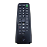
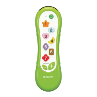
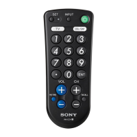
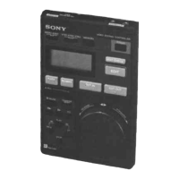
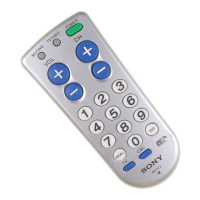
Details the function and location of the remote's various buttons and keys.

Setting the Clock

Step-by-step guide for setting the internal clock after battery installation.

Section 2: Disassembly Procedures

Case and SUB Board Disassembly

Instructions for disassembling the lower case and the SUB circuit board.

MAIN Board and LCD Unit Disassembly

Procedure for disassembling the main circuit board and LCD unit.

Section 4: Diagrams and Schematics

IC Pin Function Details

Detailed pinout and function description for the main system control IC.

MAIN Board Wiring and Schematic

Component layout and electrical schematic for the main circuit board.

SUB Board Wiring and Schematic

Component layout and electrical schematic for the sub circuit board.

Section 5: Exploded Views

Remote Control Exploded View

Visual representation of all parts with their reference numbers for assembly.

Section 6: Electrical Parts List

Main Board Component List

Detailed list of electronic components for the main circuit board.

Sub Board Component List

Detailed list of electronic components for the sub circuit board.

Related product manuals