2
TABLE OF CONTENTS
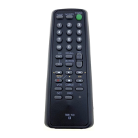
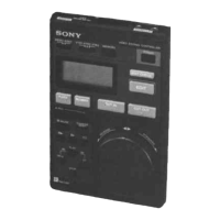
RM-AV3000
1. GENERAL ······································································ 3
2. DISASSEMBLY
2-1. Case (lower)········································································ 8
2-2. SUB Board ········································································· 8
2-3. MAIN Board and LCD Unit ··············································· 9
3. TEST MODE
3-1. EEPROM Check ······························································· 10
3-2. LCD, All Keys and EL Check ·········································· 10
4. DIAGRAMS
4-1. IC Pin Function ································································ 11
4-2. Printed Wiring Board – MAIN Board – ··························· 12
4-3. Schematic Diagram – MAIN Board – ······························ 13
4-4. Printed Wiring Board – SUB Board – ······························ 14
4-5. Schematic Diagram – SUB Board – ································· 14
5. EXPLODED VIEWS ·················································· 15
6. ELECTRICAL PARTS LIST ··································· 16
Notes on chip component replacement
•Never reuse a disconnected chip component.
• Notice that the minus side of a tantalum capacitor may be
damaged by heat.
Flexible Circuit Board Repairing
•Keep the temperature of soldering iron around 270˚C
during repairing.
• Do not touch the soldering iron on the same conductor of the
circuit board (within 3 times).
• Be careful not to apply force on the conductor when soldering
or unsoldering.