8 (E)
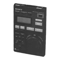
2 MONITOR connector
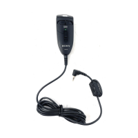
1 CAMERA connector (8-pin)
Connect to the camera using the supplied remote cable.
2 MONITOR connector (BNC)
Connect to a color monitor to observe the signal from
the camera.
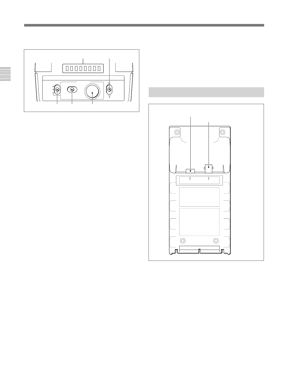
Locations and Functions of Parts
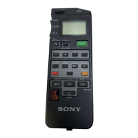
!™ MENU operation block
a Menu display (8 columns)
In normal operation mode, the display lights to show
the shutter speed, ECS frequency or S-EVS value only
when the shutter control block is operated.
When you select the RM Configuration menu, the
display shows menu items, set values, and various
information depending on operations.
b RM Configuration switch
Select the RM Configuration menu.
When this switch is pushed in the $ direction, the
“Basic menu” is selected.
When this switch is pushed in the $ direction while
holding the CANCEL/ENTER switch at ENTER, the
“Detail menu” is selected.
The RM Configuration menu is finished by pushing
this switch in the 4 direction.
c DISPLAY switch
For control of the camera’s menu.
ON: To turn on the character display function of the
camera.
OFF: To turn off the character display function of
the camera.
MENU: To set the camera in camera’s menu mode.
d CANCEL/ENTER switch
To register or cancel a menu item or value selection.
e Menu select knob (rotary encoder)
In normal operation mode, the shutter speed, ECS
frequency or S-EVS value can be adjusted with this
knob.
In camera’s menu mode, the knob is used for camera
menu operations.
On the RM Configuration menu, turn the knob to
select menu categories, subcategories, set items, set
values, and various information on the menu display.
MENU
ON
OFF
MENU
CANCEL ENTER
DISPLAY
SELECT
ab
c
d e
CAMERA MONITOR
For operations on the RM Configuration menu, see
“Settings on the RM Configuration Menu” on the next page.
For operations on the camera’s menu, refer to the
Operation Manual of the camera or the System Manual.
Note that menu mode may not be operable on some
cameras. For details, ask your Sony dealer.
Connector Panel
1 CAMERA connector