2-5
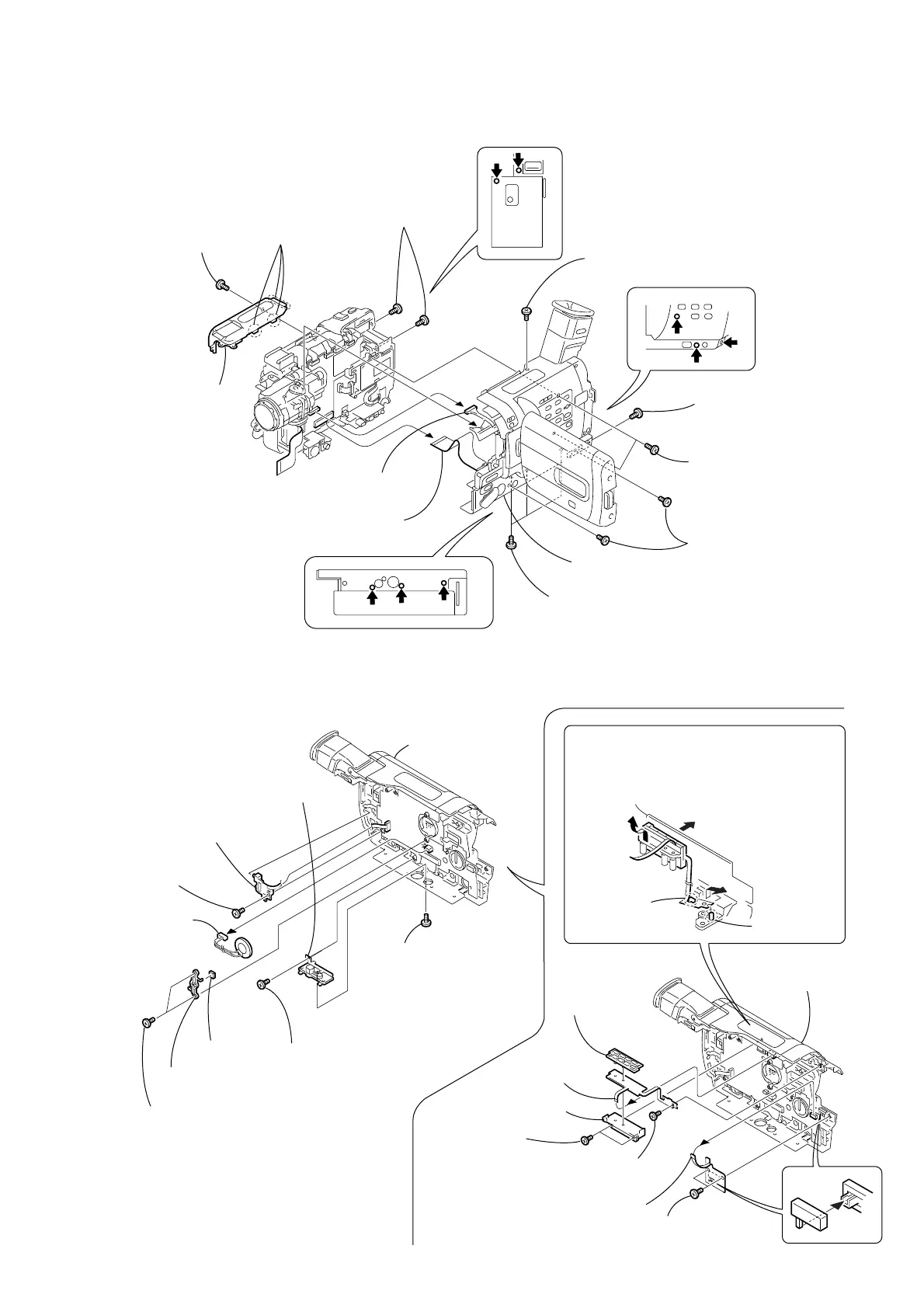
2-4. CABINET (R) SECTION
2-5. CONTROL SWITCH BLOCK (SE-1380), FP-315 BOARD
SONY
2
Three claws
5
Two MI screws
(M2
×
4) (H)
6
MI screw
(M2
×
4) (H)
7
Two tapping screws
(M1.7
×
5)
8
Two MI screws
(M2
×
4) (H)
9
Three MI screws
(M2
×
4) (H)
4
MI screw
(M2
×
4) (H)
Harness
(VP-076) (20P)
3
Cabinet
(upper)
1
MI screw
(M2
×
4) (H)
Flexible flat cable
(FFC-001) (45P)
0
Cabinet (R) block
assembly
CF-084
Board
CF-084
Board
4
Two tapping
screws (B2
×
5)
2
Two tapping
screws (B2
×
5)
8
Two tapping
screws (B2
×
5)
7
Speaker
retainer
8
Tapping screw
(B2
×
5)
9
Control switch block (SE-1380),
Culupon spacer
5
Speaker
(2.0CM)
6
Speaker
spacer
2
Tapping screw
(B2
×
5)
3
Tapping screw
(B2
×
5)
1
MI screw
(M2
×
4) (H)
3
Tripod retainer (M),
Tripod screw
6
VTR button
(M)
7
VTR holder (M)
1
FP-315 board
(8P)
9
FP-318 board
(6P)
4
Remove the FP-315 board from the dowel in
the direction
A
.
5
While pushing the ornamental cabinet (R)
outside in
B
, remove the VTR button (M)
in the direction
C
.
A
B
Claw
Dowel
0
Cabinet (R) block
assembly
0
Cabinet (R) block
assembly
REMOVING THE FP-315 BOARD
C




 To Next Page