Do you have a question about the Sony RMT-B118P and is the answer not in the manual?
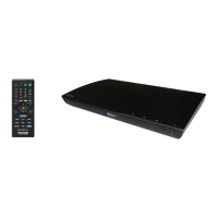
Details the technical specifications of the Blu-ray Disc/DVD player.
Procedure to test for AC leakage current from exposed metal parts to earth ground.
Information on characteristics and handling of unleaded solder used in manufacturing.
Procedure for forced ejection of a disc when the tray cannot be opened normally.
Steps required after replacing the optical device, including software setup and barcode scanning.
Lists test discs and their specifications for verifying player performance.
Detailed checks for various test disc formats to verify playback and output.
Describes the Main Menu display when a disc is inserted for BLX-104.
Details Main Menu options and sub-menu navigation for BLX-104.
Explains Sub menu1 functions and interactions with the Main Menu for BLX-104.
Details Sub menu2 functions and interactions with the Main Menu for BLX-104.
Explains Sub menu3 functions and interactions with the Main Menu for BLX-104.
Details Sub menu4 functions and interactions with the Main Menu for BLX-104.
Describes the Main Menu display when a disc is inserted for BLX-204.
Details Main Menu options and sub-menu navigation for BLX-204.
Explains Sub menu1 functions and interactions with the Main Menu for BLX-204.
Details Sub menu2 functions and interactions with the Main Menu for BLX-204.
Explains Sub menu3 functions and interactions with the Main Menu for BLX-204.
Details Sub menu4 functions and interactions with the Main Menu for BLX-204.
ESD measures and FFC holder opening instructions for drive component handling.
Flowchart for diagnosing issues within the drive (BU) section.
Detailed flowchart for checking the Optical Block Unit (BU) before replacement.
Guide for repairing/adjusting BU data to EEPROM, including requirements and remarks.
Flowchart for writing OP data to the Optical Block Unit (BU) after replacement.
Specifications for packing the KEM-470AAA/C2RP optical block.
Detailed steps for packing the KEM-470AAA/C2RP optical block into cartons.
Information on the BDPRdec.exe software for decoding BU data and its installation.
Details on loading assembly service parts, compatibility, and FFC connections.
Instructions to reuse the original laser caution label on new loading assemblies.
Details about OP data control, barcode labels, and the need for reading/saving data.
Describes the new method for obtaining and transferring BU data using digital camera and PC.
Illustrates the process of shooting barcodes, converting data, and loading it via USB.
Sequential steps for disassembling the unit, indicating page numbers for each part.
Visual guide for removing the tray cover assembly.
Step-by-step guide with images for removing the top panel.
Continuation of the top panel removal process, showing final steps and unit opening.
Instructions for removing the FR-316 board, including screws and cables.
Steps for removing the switching regulator, including ESD shield and harness.
Instructions for removing the MB-143 board, highlighting screws and flexible flat cables.
Guide for removing the BD drive unit, including screws and various flat cables.
Diagram showing the physical locations of the MB-143 board, FR-316 board, and Switching Regulator.
High-level block diagram showing the main components and their interconnections.
Detailed block diagram of the Digital Signal Processor (DSP) and related memory interfaces.
Block diagram illustrating the audio and video output sections, including HDMI and analog outputs.
Block diagram showing the USB and Ethernet interfaces and their connections.
Block diagram detailing the power supply circuits, regulators, and voltage distribution.
General notes and conventions used in the schematic diagrams, including component notations.
High-level schematic showing the overall frame and main connections of the unit.
Schematic diagrams for the FR-316 board, detailing its circuitry and connections.
Detailed schematic diagrams for the MB-143 board, covering various interfaces and functions.
Displays example waveforms for specific points on the MB-143 board for troubleshooting.
General notes and conventions for interpreting printed wiring board diagrams, including component pinouts.
Component layout diagrams for the FR-316 board (Side A and Side B).
Component layout diagrams for the MB-143 board (Side A and Side B).
Detailed pinout and function description for the MB-143 main system control IC.
Pin functions related to various audio interfaces like PWM DAC, AOSDATA, SPDIF.
Pin functions for video output signals, including VSYNC, VOUTD, and video modes.
Pin functions for the HDMI interface, including data, clock, and CEC signals.
Pin functions related to the NAND Flash interface, including chip enable and control.
Pin functions for DRAM channels, covering address, control, and data signals.
Pin functions for miscellaneous interfaces like CEC, GPIO, and JTAG.
Detailed pin functions for various GPIO ports and their alternative functions.
Pin functions for the USB interface, including power, data, and reference signals.
Pin functions for the Ethernet PHY, including power, ground, and signal lines.
Pin functions for various front-end (FE) components like motor control and laser drivers.
Continued pin functions for front-end components, including servo and tray control signals.
Procedures for entering the service mode using front panel keys or remote controller.
List and brief description of available functions within the service mode menu.
Table showing support status (supported, not supported, special control) for various functions by device.
Diagram illustrating the navigation flow and structure of the service mode menu.
Detailed instructions for selecting and activating each function within the service mode menu.
Guide to performing device tests within the Diag menu, including USB Host and IFCON tests.
Instructions for performing Video Test (Color Bar) and Audio Test (Tone Sound).
How to access and display error logs, including saving them to USB memory.
Procedure for resetting all player settings to their factory defaults.
Guide for performing Ifconfig and Ping tests to diagnose network connectivity.
Details on executing the Ping test, including IP address input and result interpretation.
Steps for updating the player's software using an update disc.
How to display system information, including drive, network, and firmware details.
Procedure for writing Optical Disc (OP) data to the drive, essential after replacement.
Table listing error codes, categories, and descriptions for diagnosing faults.
Records the version, date, and description of revisions made to the manual.
Overall troubleshooting flowchart to guide problem diagnosis and resolution.
Flowchart for diagnosing power supply and system startup issues.
Continuation of the main troubleshooting flowchart, covering various checks and component replacements.
Detailed flowchart for troubleshooting power supply issues, including voltage checks and fuse inspection.
Flowchart for diagnosing audio output problems, checking power, signals, and components.
Flowchart for diagnosing video output problems, checking power, signals, and output connectors.
Flowchart for diagnosing issues related to the FR-316 IF board and key operations.
Flowchart to troubleshoot issues where the remote control is not functioning.
Flowchart to diagnose why the white LED indicator is not lighting up.
Comprehensive flowchart for diagnosing drive-related issues, including OP data write.
Flowchart for diagnosing Ethernet connection and network update problems.
Flowchart to diagnose issues when the USB device is not recognized.
Exploded view diagram of the unit's case section with numbered parts.
Exploded view diagram of the main chassis with numbered parts.
Exploded view diagram of the BD section with numbered parts.
Lists included accessories such as cables, remote commanders, and manuals.
List of electrical parts for the FR-316 and MB-413 boards, including part numbers and descriptions.
Continued list of electrical parts for the MB-413 board, detailing capacitors and resistors.
Continued electrical parts list for MB-413, including connectors, diodes, ICs, fuses, and transistors.
Continued electrical parts list for MB-413, detailing resistors and their values.
Final part of the MB-413 electrical parts list, including variable resistors, thermistors, and crystals.
| Brand | Sony |
|---|---|
| Model | RMT-B118P |
| Category | DVD Player |
| Language | English |