EasyManua.ls Logo

Sony RMT-D166P User Manual

Sony RMT-D166P
82 pages
To Next Page IconTo Next Page
Page #1 background imageLoading...
Page #1 background image
RMT-D165A/RMT-D165P/RMT-D166P
SERVICE MANUAL
CD/DVD PLAYER
System
Laser: Semiconductor laser
Signal format system: NTSC
Audio characteristics
Frequency response: DVD VIDEO (PCM
96 kHz): 2 Hz to 44 kHz (±1.0 dB)/
DVD VIDEO (PCM 48 kHz): 2 Hz to
22 kHz (±0.5 dB)/CD: 2 Hz to 20 kHz
(±0.5 dB)
Signal-to-noise ratio (S/N ratio): 115 dB
Harmonic distortion: 0.003%
Dynamic range: DVD VIDEO: 103 dB/
CD: 99 dB
Wow and flutter: Less than detected value
(±0.001% W PEAK)
Outputs
(Jack name: Jack type/Output level/
Load impedance)
LINE OUT (AUDIO): Phono jack/
2 Vrms/ 10 kilohms
DIGITAL OUT (COAXIAL): Phono jack/
0.5 Vp-p/75 ohms
COMPONENT VIDEO OUT
(Y, PB, PR): Phono jack/Y: 1.0 Vp-p/
PB, PR: 0.65 Vp-p/75 ohms
LINE OUT (VIDEO): Phono jack/
1.0 Vp-p 75 ohms
S VIDEO OUT: 4-pin mini DIN/Y:
1.0 Vp-p, C: 0.286 Vp-p/75 ohms
General
Power requirements:
120 V AC, 60 Hz
110-240 V AC, 50/60 Hz
See page 5 for further information
Power consumption: 11 W
Dimensions (approx.): 430 × 43 ×
237.7 mm (17 × 2
11
/16 × 9
1
/2 in.)
(width/height/depth) incl. projecting
parts
Mass (approx.): 1.95 kg (4
1
/3 lb)
Operating temperature: 5°C to 35°C
(41°F to 95°F)
Operating humidity: 25% to 80%
SPECIFICATIONS
Supplied accessories
See page 17
Specifications and design are subject to
change without notice.
ENERGY STAR
is a U.S. registered
mark.
As an ENERGY STAR
Partner, Sony
Corporation has determined that this
product meets the ENERGY STA R
guidelines for energy efficiency.
Canada Model
PX Model
Mexico Model
Latin Model
Brazil Model
Hong Kong Model
GA Model
Taiwan Model
Korea Model
Saudi Arabia Model
Middle East Model
India Model
Australia Model
China Model
Argentina Model
US Model
Iran Model
DVP-NS575P
DVP-NS355/NS501P/NS507P/NS525P/NS575P/NS585P
Notes: US and Canada model only
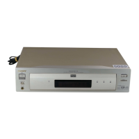
Photo : DVP-NS575P
RMT-D165P
Brazil Model
DVP-NS355
China Model
DVP-NS507P/NS525P/NS585P
Middle East Model
DVP-NS585P
US Model
DVP-NS501P

Table of Contents

Questions and Answers:

Sony RMT-D166P Specifications

General IconGeneral
BrandSony
ModelRMT-D166P
Compatible DevicesSony DVD Players
Remote Control TypeInfrared
Battery TypeAA
Device TypeDVD Player

Summary

SPECIFICATIONS

System

Details the laser type and signal format system.

Audio characteristics

Specifies frequency response, signal-to-noise ratio, and dynamic range.

Outputs

Lists output jacks, types, levels, and load impedance.

General

Provides general operating parameters like power and dimensions.

SAFETY CHECK-OUT

LEAKAGE TEST

Procedure to test for AC leakage from metal parts to earth ground.

Unleaded solder

Information about the characteristics of unleaded solder.

SERVICE NOTE

DISC REMOVAL PROCEDURE (at POWER OFF)

Method to remove a disc when the player is powered off.

Caution Point on the PWB IF-112

Important handling precaution for the IF-112 circuit board.

Precautions

On safety

Guidelines to prevent fire or shock hazards.

On power sources

Advice on AC power cord usage and disconnection.

On placement

Recommendations for unit placement to ensure ventilation.

On operation

Operational tips and warnings for using the player.

IMPORTANT NOTICE

Warning about potential permanent damage to TV screens.

About this Manual

This Player Can Play the Following Discs

Example of discs that the player cannot play

Index to Parts and Controls

Front panel display

When playing back a DVD VIDEO/DVD-RW

Front panel indicators for DVD playback status.

When playing back a VIDEO CD with Playback Control (PBC)

Front panel indicators for VCD (PBC) playback status.

When playing back a CD, DATA CD (MP3 audio), or VIDEO CD (without PBC)

Front panel indicators for CD/DATA CD playback status.

Rear panel

Remote

Guide to the Control Menu Display

List of Control Menu Items

Hooking Up the Player

Step 1: Unpacking

Lists items included in the player package.

Step 2: Inserting Batteries into the Remote

Instructions for installing batteries in the remote control.

Hookups

Step 3: Connecting the Video Cords

Guide for connecting video cables to the player and TV.

Step 4: Connecting the Audio Cords

Guide for connecting audio cables to various audio systems.

Hookups

Step 5: Connecting the Power Cord

Instructions for connecting the player's power cord.

Step 6: Quick Setup

Procedure for initial setup and basic adjustments.

Playing Discs

Playing Discs

Basic steps for inserting and playing discs.

Additional operations

Controls like CLEAR, ZOOM, and playback skip.

Locking the disc tray (Child Lock)

Feature to prevent children from opening the disc tray.

Resuming Playback from the Point Where You Stopped the Disc (Multi-disc Resume)

Using the DVD's Menu

Selecting "ORIGINAL" or "PLAY LIST" on a DVD-RW DISC

Playing VIDEO CDs with PBC Functions (PBC Playback)

Various Play Mode Functions (Program Play, Shuffle Play, Repeat Play, A-B Repeat Play)

Creating your own program (Program Play)

How to arrange titles, chapters, or tracks for custom playback.

Playing in random order (Shuffle Play)

Playing repeatedly (Repeat Play)

Repeating a specific portion (A-B Repeat Play)

Searching for a Scene

Searching for a Particular Point on a Disc (Search, Scan, Slow-motion Play, Freeze Frame)

Methods to find specific points on a disc using various search modes.

Watching frame by frame (Slow-motion play)

Viewing content frame-by-frame during playback.

Searching for a Title/Chapter/Track/Scene, etc.

Viewing Information About the Disc

Checking the Playing Time and Remaining Time

Displaying the current playing time and remaining time.

Viewing Information About the Disc

Checking the play information of the Disc (DVD/CD text)

Displaying disc metadata like text and track names.

Checking the information on the front panel display

Viewing playback information on the unit's front panel.

Sound Adjustments

Changing the Sound

Selecting audio output modes and channels.

Checking the audio signal format

Displaying the current audio signal type (e.g., PCM, Dolby).

TV Virtual Surround Settings (TVS)

Enabling and configuring virtual surround sound effects.

Enjoying Movies

Changing the Angles

Selecting different camera angles for DVD content.

Displaying the Subtitles

Controlling the display of subtitles during playback.

Adjusting the Playback Picture (CUSTOM PICTURE MODE)

Customizing picture settings like contrast and brightness.

Sharpening the Outline of an Image (SHARPNESS)

Adjusting the sharpness of the image outlines.

Playing a DATA CD

About MP3 Audio Tracks and JPEG Image Files

Information on MP3 audio and JPEG image file formats.

Playing DATA CDs with MP3 Audio Tracks and JPEG Image Files

Selecting an album from a DATA CD

Choosing albums from DATA CDs for playback.

Selecting an MP3 audio track from a DATA CD

Selecting specific MP3 tracks from DATA CDs.

Playing DATA CDs with MP3 Audio Tracks and JPEG Image Files

Selecting a JPEG image file from a DATA CD

Selecting specific JPEG image files from DATA CDs.

Playing Audio Tracks and Images as a Slideshow with Sound

Creating slideshows with synchronized audio.

Rotating a JPEG image

Rotating displayed JPEG images by 90-degree increments.

Magnifying a JPEG image

Zooming in on JPEG images for detailed viewing.

Playing a DATA CD

Specifying the slideshow duration

Setting the display time for each image in a slideshow.

Selecting an effect for image files in the slideshow

Applying visual transition effects to slideshow images.

Locking Discs (CUSTOM PARENTAL CONTROL, PARENTAL CONTROL)

Setting playback restrictions for discs via parental controls.

Using Various Additional Functions

Custom Parental Control

Setting personalized parental control levels and passwords.

Parental Control (limited playback)

Applying playback limitations based on age ratings.

Controlling Your TV with the Supplied Remote

Using the player remote to control a Sony TV.

Settings and Adjustments

Using the Setup Display

Navigating the setup menu for various player settings.

Setting the Display or Sound Track Language (LANGUAGE SETUP)

Configuring on-screen display and audio track languages.

Settings for the Display (SCREEN SETUP)

Adjusting display-related options like TV type and aspect ratio.

Settings and Adjustments

Settings for the Sound (AUDIO SETUP)

Configuring audio output settings like DRC and downmix.

Additional Information

Troubleshooting

Guide to resolving common operational issues.

Troubleshooting

Power

Troubleshooting steps for issues related to the power supply.

Picture

Troubleshooting steps for video output problems.

Sound

Troubleshooting steps for audio output problems.

Operation

The remote does not function.

Troubleshooting steps when the remote control is unresponsive.

The disc does not play.

Resolving issues when a disc fails to play correctly.

The MP3 audio track cannot be played

Troubleshooting problems with MP3 audio track playback.

Self-diagnosis Function (When letters/numbers appear in the display)

Interpreting self-diagnosis error codes displayed on the unit.

Glossary

SECTION 3 BLOCK DIAGRAMS

3-1. OVERALL BLOCK DIAGRAM

High-level block diagram showing the system architecture.

3-2. SYSTEM CONTROL/SIGNAL PROCESSOR BLOCK DIAGRAM

3-3. RF/SERVO BLOCK DIAGRAM

3-4. AUDIO BLOCK DIAGRAM

3-5. VIDEO BLOCK DIAGRAM

3-6. INTERFACE CONTROL BLOCK DIAGRAM

3-7. POWER BLOCK DIAGRAM

SECTION 4 PRINTED WIRING BOARDS AND SCHEMATIC DIAGRAMS

4-1. FRAME SCHEMATIC DIAGRAM

Overall schematic diagram showing the unit's layout.

4-2. PRINTED WIRING BOARDS AND SCHEMATIC DIAGRAMS

For printed wiring boards

Conventions and notes for printed wiring board diagrams.

For schematic diagrams

Conventions and notes for schematic diagrams.

4-3. WAVEFORM

Section detailing signal waveforms.

MV-044 BOARD (DRIVE, CPU, SERVO-DSP, AVDEC, VIDEO, AUDIO, PS THROUGH) PRINTED WIRING BOARD

MV-044 BOARD (1/5)

MV-044 BOARD (1/5) SCHEMATIC DIAGRAM

Part 1 of the MV-044 board schematic diagram.

MV-044 BOARD (2/5)

MV-044 BOARD (2/5) SCHEMATIC DIAGRAM

Part 2 of the MV-044 board schematic diagram.

MV-044 BOARD (3/5)

MV-044 BOARD (3/5) SCHEMATIC DIAGRAM

Part 3 of the MV-044 board schematic diagram.

MV-044 BOARD (4/5)

MV-044 BOARD (4/5) SCHEMATIC DIAGRAM

Part 4 of the MV-044 board schematic diagram.

MV-044 BOARD (5/5)

MV-044 BOARD (5/5) SCHEMATIC DIAGRAM

Part 5 of the MV-044 board schematic diagram.

IF-112 (INTERFACE) PRINTED WIRING BOARD

IF-112 BOARD A SIDE

View of the IF-112 board's component side.

IF-112 BOARD B SIDE

View of the IF-112 board's solder side.

IF-112 BOARD

IF-112 BOARD SCHEMATIC DIAGRAM

Circuit schematic diagram for the IF-112 interface board.

POWER BLOCK (SRV1487UC) PRINTED WIRING BOARD

POWER BOARD (SRV1487UC) (SIDE A)

View of the SRV1487UC power board's component side.

POWER BOARD (SRV1487UC) (SIDE B)

View of the SRV1487UC power board's solder side.

POWER BOARD

POWER BLOCK (SRV1487UC) (US, CND, MX) SCHEMATIC DIAGRAM

Schematic diagram for the SRV1487UC power board.

POWER BLOCK (SRV1501WW) PRINTED WIRING BOARD

POWER BOARD (SRV1501WW) (SIDE A)

View of the SRV1501WW power board's component side.

POWER BOARD (SRV1501WW) (SIDE B)

View of the SRV1501WW power board's solder side.

POWER BOARD

POWER BLOCK (SRV1501WW) (E, SP, AUS) SCHEMATIC DIAGRAM

Schematic diagram for the SRV1501WW power board.

SECTION 5 IC PIN FUNCTION DESCRIPTION

5-1. SYSTEM CONTROL PIN FUNCTION (MV-044 BOARD IC201)

Pinout and function details for the system control IC.

5-1. SYSTEM CONTROL PIN FUNCTION (MV-044 BOARD IC201)

5-1. SYSTEM CONTROL PIN FUNCTION (MV-044 BOARD IC201)

5-1. SYSTEM CONTROL PIN FUNCTION (MV-044 BOARD IC201)

5-1. SYSTEM CONTROL PIN FUNCTION (MV-044 BOARD IC201)

5-1. SYSTEM CONTROL PIN FUNCTION (MV-044 BOARD IC201)

5-1. SYSTEM CONTROL PIN FUNCTION (MV-044 BOARD IC201)

SECTION 6 TEST MODE

6-1. GENERAL DESCRIPTION

Overview of test mode functions and requirements.

6-2. STARTING TEST MODE

Steps to enter the diagnostic test mode.

6-3. DRIVE MANUAL OPERATION

Manual control functions for the disc drive system.

6-4. MIRROR TIME ADJUSTMENT

Procedure for adjusting mirror time values for discs.

6-4-1. EXECUTING MIRROR TIME ADJUSTMENT

Step-by-step guide for performing mirror time adjustment.

6-4. MIRROR TIME ADJUSTMENT

6-5. EXECUTING IOP MEASUREMENT

Procedure for executing the IOP measurement.

6-5. EXECUTING IOP MEASUREMENT

6-6. IF CON SELF DIAGNOSTIC FUNCTION

1. IF-112 BOARD (IF CON) TEXT MODE

Description of the IF CON self-diagnosis mode.

2. OPERATION OF SELF CHECK MODE

Overview of the self-check mode for basic testing.

2-1. Self Check Mode Transition Processing

Steps to transition into the Self Check Mode.

2-2. Operation of Auto Self Check

2-3. Each Self Check Function

2-3-1. FLD and LED AII ON

Test for FLD display and all LEDs activation.

2-3-2. Main Unit Key Name Display and Key Code Display

Test for main unit key inputs and their code display.

2-3-3. Remote Commander Key Name Display and Key Code Display

2-3-4. Communication Monitoring Display

2-3-5. FLD Anode Test Display and SHUTTLE Click Operation Test

2-3-5. FLD Anode Test Display and SHUTTLE Click Operation Test

2-3-6. FLD Grid Test Display and SHUTTLE Click Operation Test

2-3-7. LED Test Display

2-3-7. LED Test Display

ANODE CONNECTION

SECTION 7 ELECTRICAL ADJUSTMENT

7-1. POWER SUPPLY ADJUSTMENT

Steps to adjust and verify power supply voltages.

8-1. EXPLODED VIEWS

8-1-1. MAIN SECTION

Exploded view of the main unit assembly.

8-1. EXPLODED VIEWS

8-1-2. MECHANISM DECK ASSEMBLY

Exploded view of the disc mechanism deck.

IF-112

8-2. ELECTRICAL PARTS LIST

List of electrical components for the IF-112 board.

IF-112

8-2. ELECTRICAL PARTS LIST (continued)

Continuation of the electrical parts list for the IF-112 board.

IF-112 MV-044

8-2. ELECTRICAL PARTS LIST (continued)

Continuation of the electrical parts list for MV-044 board.

MV-044

8-2. ELECTRICAL PARTS LIST (continued)

Continuation of the electrical parts list for the MV-044 board.

MV-044

8-2. ELECTRICAL PARTS LIST (continued)

Continuation of the electrical parts list for the MV-044 board.

MV-044

8-2. ELECTRICAL PARTS LIST (continued)

Continuation of the electrical parts list for the MV-044 board.

MV-044

8-2. ELECTRICAL PARTS LIST (continued)

Continuation of the electrical parts list for the MV-044 board.

MV-044

8-2. ELECTRICAL PARTS LIST (continued)

Continuation of the electrical parts list for the MV-044 board.

MV-044

8-2. ELECTRICAL PARTS LIST (continued)

Continuation of the electrical parts list for the MV-044 board.

Related product manuals