RMT-D152A/D156P/D157P/D152E/D153A/D158P
DVP-NS325/NS330/NS333/NS430/NS433/NS530/NS725P/NS730P
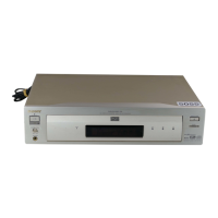
Photo : DVP-NS325
RMT-D152A
SERVICE MANUAL
CD/DVD PLAYER
System
Laser: Semiconductor laser
Signal format system: NTSC
Audio characteristics
Frequency response: DVD VIDEO (PCM
96 kHz): 2 Hz to 44 kHz (±1.0 dB)/
DVD VIDEO (PCM 48 kHz): 2 Hz to
22 kHz (±0.5 dB)/CD: 2 Hz to 20 kHz
(±0.5 dB)
Signal-to-noise ratio (S/N ratio): 115 dB
(LINE OUT (L/R) AUDIO jacks only)
Harmonic distortion: 0.003%
Dynamic range: DVD VIDEO: 103 dB/
CD: 99 dB
Wow and flutter: Less than detected
value (±0.001% W PEAK)
The signals from LINE OUT L/R
(AUDIO) jacks are measured. When you
play PCM sound tracks with a 96 kHz
sampling frequency, the output signals
from the DIGITAL OUT (COAXIAL) jack
are converted to 48 kHz sampling
frequency.
Outputs/Inputs (NS325)
Jack name: (Jack type/Output or
Input level/Load impedance)
Outputs (NS725P/NS530/NS730P/
NS330/NS333/NS430/NS433)
Jack name: (Jack type/Output level/
Load impedance)
LINE OUT (AUDIO): Phono jack/
2 Vrms/ 10 kilohms
DIGITAL OUT (OPTICAL): Optical
output jack/-18d Bm (wave length:
660 nm) (NS725P/NS530/NS730P/
NS430/NS433)
DIGITAL OUT (COAXIAL): Phono jack/
0.5 Vp-p/75 ohms (NS325/NS725P/
NS530/NS730P/NS330/NS333/
NS430/NS433)
COMPONENT VIDEO OUT (Y, P
B, PR):
Phono jack/Y: 1.0 Vp-p/PB, PR:
0.65 Vp-p/75 ohms (NS325/NS725P)
COMPONENT VIDEO OUT (Y, P
B/CB,
PR/CR): Phono jack/Y: 1.0 Vp-p,
P
B/CB, PR/CR: 0.7 Vp-p/75 ohms
(NS730P)
COMPONENT VIDEO OUT (Y, CB/CR):
Phono jack/Y: 1.0 Vp-p, C
B, CR:
0.7 Vp-p/75 ohms (NS530)
LINE OUT (VIDEO): Phono jack/
1.0 Vp-p 75 ohms (NS325/NS725P/
NS530/NS730P/NS330/NS333/
NS430/NS433)
S VIDEO OUT: 4-pin mini DIN/Y:
1.0 Vp-p, C: 0.286 Vp-p/75 ohms
(NS325/NS725P/NS530/NS730P/
NS330/NS333/NS430/NS433)
SPECIFICATIONS
General
Power consumption: 13 W/ 14 W
Dimensions (approx.): 430 × 55.5 ×
244 mm (17 × 2
3
/16 × 9
5
/8 in.)
(NS325/NS530/NS330/NS333)
430 × 55.5 × 237 mm (17 × 2
3
/16 ×
9
3
/5 in.) (NS430/NS433/NS725P/
NS730P)
Supplied accessories
See page 14 (NS325)
See page 15 (NS725P/NS530/NS730P/
NS330/NS333/NS430/NS433)
Specifications and design are subject to
change without notice.
ENERGY STAR
is a U.S. registered
mark.
As an
ENERGY STAR
Partner, Sony
Corporation has determined that this
product meets the
ENERGY STA R
guidelines for energy efficiency.
US Model
DVP-NS325/NS725P
Canadian Model
DVP-NS325/NS725P
PX Model
DVP-NS325/NS725P
E Model
DVP-NS325
Mexico Model
DVP-NS325
Brazilian Model
DVP-NS325
Argentina Model
DVP-NS325
AEP Model
DVP-NS330/NS333/NS430/
NS433
UK Model
DVP-NS330/NS430
Russian Model
DVP-NS330
Hong Kong Model
DVP-NS530/NS730P
Singapore Model
DVP-NS530/NS730P
Taiwan Model
DVP-NS530
Korea Model
DVP-NS530/NS730P
Saudi Arabia Model
DVP-NS530
Middle East Model
DVP-NS530/NS730P
Australian Model
DVP-NS530/NS730P
New Zealand Model
DVP-NS530/NS730P


