EasyManua.ls Logo

Sony RMT-D157P User Manual

Sony RMT-D157P
133 pages
To Next Page IconTo Next Page
Page #1 background imageLoading...
Page #1 background image
RMT-D152A/D156P/D157P/D152E/D153A/D158P
DVP-NS325/NS330/NS333/NS430/NS433/NS530/NS725P/NS730P
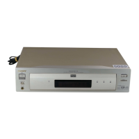
Photo : DVP-NS325
RMT-D152A
SERVICE MANUAL
CD/DVD PLAYER
System
Laser: Semiconductor laser
Signal format system: NTSC
Audio characteristics
Frequency response: DVD VIDEO (PCM
96 kHz): 2 Hz to 44 kHz (±1.0 dB)/
DVD VIDEO (PCM 48 kHz): 2 Hz to
22 kHz (±0.5 dB)/CD: 2 Hz to 20 kHz
(±0.5 dB)
Signal-to-noise ratio (S/N ratio): 115 dB
(LINE OUT (L/R) AUDIO jacks only)
Harmonic distortion: 0.003%
Dynamic range: DVD VIDEO: 103 dB/
CD: 99 dB
Wow and flutter: Less than detected
value (±0.001% W PEAK)
The signals from LINE OUT L/R
(AUDIO) jacks are measured. When you
play PCM sound tracks with a 96 kHz
sampling frequency, the output signals
from the DIGITAL OUT (COAXIAL) jack
are converted to 48 kHz sampling
frequency.
Outputs/Inputs (NS325)
Jack name: (Jack type/Output or
Input level/Load impedance)
Outputs (NS725P/NS530/NS730P/
NS330/NS333/NS430/NS433)
Jack name: (Jack type/Output level/
Load impedance)
LINE OUT (AUDIO): Phono jack/
2 Vrms/ 10 kilohms
DIGITAL OUT (OPTICAL): Optical
output jack/-18d Bm (wave length:
660 nm) (NS725P/NS530/NS730P/
NS430/NS433)
DIGITAL OUT (COAXIAL): Phono jack/
0.5 Vp-p/75 ohms (NS325/NS725P/
NS530/NS730P/NS330/NS333/
NS430/NS433)
COMPONENT VIDEO OUT (Y, P
B, PR):
Phono jack/Y: 1.0 Vp-p/PB, PR:
0.65 Vp-p/75 ohms (NS325/NS725P)
COMPONENT VIDEO OUT (Y, P
B/CB,
PR/CR): Phono jack/Y: 1.0 Vp-p,
P
B/CB, PR/CR: 0.7 Vp-p/75 ohms
(NS730P)
COMPONENT VIDEO OUT (Y, CB/CR):
Phono jack/Y: 1.0 Vp-p, C
B, CR:
0.7 Vp-p/75 ohms (NS530)
LINE OUT (VIDEO): Phono jack/
1.0 Vp-p 75 ohms (NS325/NS725P/
NS530/NS730P/NS330/NS333/
NS430/NS433)
S VIDEO OUT: 4-pin mini DIN/Y:
1.0 Vp-p, C: 0.286 Vp-p/75 ohms
(NS325/NS725P/NS530/NS730P/
NS330/NS333/NS430/NS433)
SPECIFICATIONS
General
Power consumption: 13 W/ 14 W
Dimensions (approx.): 430 × 55.5 ×
244 mm (17 × 2
3
/16 × 9
5
/8 in.)
(NS325/NS530/NS330/NS333)
430 × 55.5 × 237 mm (17 × 2
3
/16 ×
9
3
/5 in.) (NS430/NS433/NS725P/
NS730P)
Supplied accessories
See page 14 (NS325)
See page 15 (NS725P/NS530/NS730P/
NS330/NS333/NS430/NS433)
Specifications and design are subject to
change without notice.
ENERGY STAR
is a U.S. registered
mark.
As an
ENERGY STAR
Partner, Sony
Corporation has determined that this
product meets the
ENERGY STA R
guidelines for energy efficiency.
US Model
DVP-NS325/NS725P
Canadian Model
DVP-NS325/NS725P
PX Model
DVP-NS325/NS725P
E Model
DVP-NS325
Mexico Model
DVP-NS325
Brazilian Model
DVP-NS325
Argentina Model
DVP-NS325
AEP Model
DVP-NS330/NS333/NS430/
NS433
UK Model
DVP-NS330/NS430
Russian Model
DVP-NS330
Hong Kong Model
DVP-NS530/NS730P
Singapore Model
DVP-NS530/NS730P
Taiwan Model
DVP-NS530
Korea Model
DVP-NS530/NS730P
Saudi Arabia Model
DVP-NS530
Middle East Model
DVP-NS530/NS730P
Australian Model
DVP-NS530/NS730P
New Zealand Model
DVP-NS530/NS730P

Table of Contents

Questions and Answers:

Sony RMT-D157P Specifications

General IconGeneral
TypeRemote Control
BrandSony
ModelRMT-D157P
Remote Control TypeInfrared
Battery TypeAA
Number of Batteries2
Compatible DevicesDVD player

Summary

SPECIFICATIONS

General

Provides details on power consumption, dimensions, and supplied accessories for various models.

Supplied accessories

Lists the accessories supplied with the player, referring to specific pages for details.

SAFETY CHECK-OUT

LEAKAGE TEST

Details the procedure and methods for testing AC leakage to earth ground.

Unleaded solder

Explains the characteristics and handling precautions for unleaded solder.

SERVICE NOTE

Disc Removal Procedure (at POWER OFF)

Describes the specific steps for removing a disc when the player is powered off.

How to Service MB-108 Board

Provides instructions and diagrams for servicing the MB-108 board.

GENERAL

Precautions

Covers essential safety, power, placement, and operation guidelines for the player.

About this Manual

Explains the manual's structure, including icon meanings and disc compatibility.

This Player Can Play the Following Discs

Lists the types of discs supported by the player, including trademarks.

Example of discs that the player cannot play

Details discs that are not compatible with the player due to format or region codes.

Notes about the Discs

Provides guidance on handling discs, cleaning, and compatibility with protected music.

Note on playback operations of DVDs and VIDEO CDs

Explains that disc content may affect playback features and refers to disc instructions.

Copyrights

Details copyright protection technology and usage restrictions.

Guide to the Control Menu Display

Control Menu Display

Explains how to use the Control Menu to select functions and view information during playback.

Hookups

Hooking Up the Player

Provides a step-by-step guide for connecting the player to a TV or AV amplifier.

Step 1: Unpacking

Lists the items included in the player package and unpacking checks.

Step 2: Inserting Batteries into the Remote

Details how to insert batteries into the remote commander for operation.

Step 3: Connecting the Video Cords

Explains how to connect video output jacks to a TV, projector, or AV amplifier.

Playing Discs

Playing Discs

Describes the basic procedure for playing discs, including starting and stopping playback.

Locking the disc tray (Child Lock)

Explains how to lock the disc tray to prevent unauthorized access.

Resuming Playback from the Point Where You Stopped the Disc (Multi-disc Resume)

Details the multi-disc resume function that remembers playback points for multiple discs.

Searching for a Scene

Searching for a Particular Point on a Disc (Scan, Slow-motion Play, Search, Freeze Frame)

Covers various methods for navigating within a disc, like scanning and slow-motion.

Searching for a Title/Chapter/Track/Scene, etc. (Search mode)

Explains how to search for specific content by title, chapter, track, or time code.

Viewing Information About the Disc

Checking the Playing Time and Remaining Time

Shows how to check the playing time and remaining time of discs.

Checking the information on the front panel display

Explains how front panel display information changes with TV screen display.

Checking the Play Information

Details how to check disc playback information like bit rate and layer.

Sound Adjustments

Changing the Sound

Describes how to change audio formats, languages, and channel selection.

TV Virtual Surround Settings (TVS)

Explains how to activate TV Virtual Surround for simulated surround sound effects.

Displaying the Subtitles

Covers how to display, change, or turn off subtitles for DVDs.

Adjusting the Picture Quality (BNR)

Explains the Block Noise Reduction feature to reduce picture noise.

Enjoying Movies

Adjusting the Playback Picture (CUSTOM PICTURE MODE)

Details how to adjust picture quality settings for optimal viewing.

Enhancing the Playback Picture (DIGITAL VIDEO ENHANCER)

Describes the DVE function for enhancing picture clarity and sharpness.

Changing the Angles

Explains how to switch between different viewing angles on DVDs.

Locking Discs (CUSTOM PARENTAL CONTROL, PARENTAL CONTROL)

Custom Parental Control

Allows setting custom playback restrictions for up to 40 discs using a password.

Parental Control (limiting playback by children)

Enables setting playback limitation levels based on age or region.

Using Various Additional Functions

Changing the password

Provides instructions for changing the parental control password.

Controlling Your TV with the Supplied Remote

Explains how to use the remote to control Sony TV functions like power and volume.

Settings and Adjustments

Using the Setup Display

Guides through making various adjustments via the Setup Display menu.

Setting the Display or Sound Track Language (LANGUAGE SETUP)

Allows setting languages for the on-screen display, menus, audio, and subtitles.

SECTION 2 DISASSEMBLY

2-1. UPPER CASE

Provides instructions for removing the upper case of the player unit.

2-2. FRONT PANEL ASSEMBLY

Details the steps for removing the front panel assembly.

2-3. LOADING ASSEMBLY

Explains the procedure for disassembling the loading mechanism.

2-4. OPTICAL DEVICE (KHM-290AAA)

Provides instructions for removing and handling the optical pickup device.

2-5. DC MOTOR and MS128 BOARD

Details the disassembly of the DC motor and the MS-128 board.

2-6. ER-21 BOARD

Provides instructions for accessing and removing the ER-21 circuit board.

2-7. AF-098 BOARD

Details the disassembly procedure for the AF-098 circuit board.

2-8. MB-108 BOARD

Provides instructions for accessing and removing the MB-108 circuit board.

2-9. SWITCHING REGULATOR

Explains the disassembly steps for the switching regulator component.

2-10. INTERNAL VIEWS

Shows visual references of the player's internal components.

2-11. CIRCUIT BOARDS LOCATION

Illustrates the physical location of various circuit boards within the player.

SECTION 3 BLOCK DIAGRAMS

3-1. OVERALL BLOCK DIAGRAM

Presents a high-level overview of the player's system architecture.

3-2. SYSTEM CONTROL BLOCK DIAGRAM

Illustrates the system control functions and their interconnections.

3-3. RF/SERVO BLOCK DIAGRAM

Details the RF and servo control systems for disc reading.

3-4. SIGNAL PROCESSOR BLOCK DIAGRAM

Shows the signal processing path for audio and video data.

3-5. AUDIO BLOCK DIAGRAM

Illustrates the audio signal flow and processing within the player.

3-6. VIDEO BLOCK DIAGRAM

Details the video signal path and processing.

3-7. INTERFACE CONTROL BLOCK DIAGRAM

Shows the control logic for various interfaces.

3-8. POWER BLOCK DIAGRAM (1/3)

Illustrates the first part of the power supply block diagram.

SECTION 4 PRINTED WIRING BOARDS AND SCHEMATIC DIAGRAMS

4-1. FRAME SCHEMATIC DIAGRAM

Provides the overall schematic diagram for the player's frame.

4-2. PRINTED WIRING BOARDS AND SCHEMATIC DIAGRAMS

Contains detailed printed wiring boards and schematic diagrams for various boards.

SECTION 5 IC PIN FUNCTION DESCRIPTION

5-1. SYSTEM CONTROL PIN FUNCTION (MB-108 BOARD IC104: MB91307RPFV-G-BND-E1)

Details the pin functions for the System Control IC on the MB-108 board.

SECTION 6 TEST MODE

6-1. GENERAL DESCRIPTION

Explains the purpose and basic operation of the Test Mode.

6-2. STARTING TEST MODE

Describes the procedure to enter the Test Mode using the remote commander.

6-3. SYSCON DIAGNOSIS

Details how to perform system control diagnostics via the remote commander.

6-4. DRIVE AUTO ADJUSTMENT

Explains the automated process for adjusting drive mechanisms.

6-5. DRIVE MANUAL OPERATION

Guides on manually controlling and adjusting servo functions.

6-6. MECHA AGING

Describes the mechanism aging test procedure.

6-7. EMERGENCY HISTORY

Explains how to display and clear emergency history logs.

6-8. VERSION INFORMATION

Details how to check software versions and checksums.

6-9. VIDEO LEVEL ADJUSTMENT

Describes the procedure for adjusting video levels using color bars.

SECTION 6 TEST MODE

6-10. IF CON SELF DIAGNOSTIC FUNCTION

Explains the IF CON self-diagnostic functions and test modes.

2. OPERATION OF SELF CHECK MODE

Details how to transition to and operate the Self Check Mode.

SECTION 6 TEST MODE

2-3. Each Self Check Function

Describes specific self-check functions testing FLD, LED, and keys.

SECTION 6 TEST MODE

6-11. TROUBLESHOOTING

Provides solutions for common problems encountered during testing or operation.

SECTION 6 TEST MODE

6-5. DRIVE MANUAL OPERATION

Details manual control for servo, track, and layer adjustments.

0. Disc Check Memory

Explains the process of measuring mirror time to check disc type.

1. Disc Type

Guides on setting the correct disc type for proper operation.

SECTION 6 TEST MODE

1. Disc Type

Lists disc types and how to set them for adjustment.

2. Servo Control

Details servo on/off controls and their functions for replay.

SECTION 6 TEST MODE

3. Track/Layer Jump

Explains how to perform track and layer jumps for DVD-DL discs.

4. Manual Adjustment

Guides on manually adjusting parameters like tracking offset and focus gain.

SECTION 6 TEST MODE

5. Auto Adjustment

Describes the automatic adjustment of various servo and tracking parameters.

6. Memory Check

Explains how to inspect adjusted data stored in the EEPROM.

SECTION 6 TEST MODE

6-6. MECHA AGING

Details the procedure for the mechanism aging test.

6-7. EMERGENCY HISTORY

Explains how to display and clear emergency history information.

6-8. VERSION INFORMATION

Shows how to check ROM versions, region codes, and other system information.

6-9. VIDEO LEVEL ADJUSTMENT

Describes the video level adjustment process using color bars.

SECTION 6 TEST MODE

6-10. IF CON SELF DIAGNOSTIC FUNCTION

Details the IF CON self-diagnostic functions and test modes.

2. OPERATION OF SELF CHECK MODE

Explains how to transition to and operate the Self Check Mode.

SECTION 6 TEST MODE

2-3. Each Self Check Function

Describes specific self-check functions testing FLD, LED, and keys.

SECTION 6 TEST MODE

6-11. TROUBLESHOOTING

Provides solutions for common problems encountered during testing or operation.

SECTION 7 ELECTRICAL ADJUSTMENT

7-1. POWER SUPPLY CHECK

Details the procedure for checking power supply voltages against specifications.

7-2. ADJUSTMENT OF VIDEO SYSTEM

1. Video Level Adjustment (MB-108 BOARD)

Describes the primary video level adjustment for correct brightness.

2. Checking S Video Output S-Y

Checks the S-Video output S-Y level for correct picture display.

3. Checking S Video Output S-C

Checks the S-Video output S-C level for correct color saturation.

4. Checking Component Video Output Y

Checks the component video output Y level for correct brightness.

7-2. ADJUSTMENT OF VIDEO SYSTEM

5. Checking Component Video Output B-Y

Checks the component video output B-Y level for correct color.

6. Checking Component Video Output R-Y

Checks the component video output R-Y level for correct color.

7-3. ADJUSTMENT RELATED PARTS ARRANGEMENT

SECTION 8 REPAIR PARTS LIST

8-1. EXPLODED VIEWS

Provides visual breakdowns of the player's mechanical and electronic assemblies.

8-1. EXPLODED VIEWS

8-1-1. MAIN SECTION

Details the parts list for the main mechanical section of the player.

8-1. EXPLODED VIEWS

8-1-2. MECHANISM DECK ASSEMBLY

Lists the parts for the mechanism deck assembly, including motors and belts.

8-2. ELECTRICAL PARTS LIST

Related product manuals