Do you have a question about the Sony RMT-D187A and is the answer not in the manual?
Details on system components, outputs, and their technical specifications.
Covers power requirements, dimensions, mass, operating conditions, and accessories.
Verification of connections, parts, and wiring after service.
Method for measuring AC leakage current from exposed metal parts.
Characteristics of lead-free solder and its application.
Pinout and function of the main control IC (IC101) on MV-60/62 boards.
Routing guidelines for USB harnesses on MV-60 and MV-62 boards.
Steps for removing a disc from the player when it is powered off.
How to disable the child lock feature on the disc tray.
Guidance on checking model name after replacing circuit boards.
Safety warnings, handling precautions, and notes on disc handling.
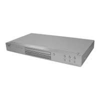
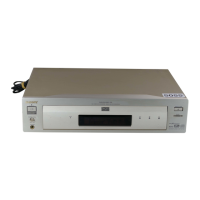
Identification of main controls and parts on the player and remote.
Instructions for connecting the player to a TV and configuring basic settings.
Diagrams of panels and steps to connect the player to a TV.
Instructions for connecting audio equipment and the power cord.
Guided setup for language, screen, and audio connections.
Explanation of PROGRAM, SHUFFLE, REPEAT, and A-B REPEAT playback modes.
How to connect and use USB devices for playback on specific models.
Instructions for playing discs and using HDMI one-touch playback feature.
Explanation of various functions accessible via the Control Menu.
How to use BRAVIA Sync features for player control via TV.
How to play various media file types from discs or USB devices.
Instructions for photo slideshows, including interval and effect settings.
Overview of accessing and using the player's setup menus.
How to set OSD, Menu, Audio, and Screen settings.
Detailed adjustments for playback features like Auto Power Off, Black Level, etc.
Configuration for sound output, DRC, downmixing, and digital audio formats.
Adjusting HDMI resolution, JPEG resolution, and Control for HDMI.
Solutions for common problems with power, picture, sound, and operation.
Interpreting error codes displayed by the player's self-diagnosis system.
Steps for removing the upper case and front panel assembly.
Procedure for disassembling the disc loading mechanism.
Disassembly of the optical pick-up and its holder assembly.
Disassembly of rear panel, MV-60, and IF-163 boards for non-Euro models.
Disassembly of rear panel, MV-62, and IF-163 boards for Euro models.
Procedure for removing the switching regulator board.
Visual overview of the player's internal components from top and bottom.
Diagram showing the location of various circuit boards within the player.
A high-level overview of the player's main functional blocks and their interconnections.
Diagram illustrating the power supply and distribution paths within the player.
Detailed diagram of the main processor, memory, and signal processing functions.
Diagram showing the RF signal processing and servo control systems for disc playback.
Diagram illustrating the video signal processing paths, including output stages.
Diagram showing the audio signal processing and output circuits.
Diagram of the interface control board (IF-163) and its connections.
Schematic diagram for the MV-60 board, detailing its components and connections.
Schematic diagram for the MV-62 board, detailing its components and connections.
Visual representations of key signal waveforms for the MV-60 and MV-62 boards.
Printed wiring board layout for the IF-163 interface board (Side A and B).
Schematic diagram for the IF-163 interface board, showing its circuitry.
Printed wiring board layout for the FB-224 USB interface board (Side A and B).
Printed wiring board layout for the MS-203 loading motor board.
Printed wiring board layout for the MV-60 board (Side A and B).
Printed wiring board layout for the MV-62 board (Side A and B).
Schematic diagram for the MV-60 board's system and servo functions.
Schematic diagram for the MV-60 board's video and audio signal paths.
Schematic diagram for the MV-62 board's system and servo functions.
Schematic diagram for the MV-62 board's video signal processing.
Schematic diagram for the MV-62 board's audio signal processing.
Printed wiring board layout for the SRV2187UC switching regulator (Side A and B).
Schematic diagram for the SRV2187UC switching regulator board.
Printed wiring board layout for the SRV2186WW switching regulator (Side A and B).
Schematic diagram for the SRV2186WW switching regulator board.
Pinout and function of the main control IC (IC101) on MV-60/62 boards.
Procedure for performing Input/Output Port measurement using the test mode.
How to access and interpret the player's emergency history log.
Procedure to reset player setup data to factory defaults via test mode.
How to check firmware version details for the main unit, RISC, and DSPs.
Test mode for diagnosing IF-163 board functions and communication.
Sequence of displays during the automatic self-check mode.
Testing of FLD, LED display, and key input functions in self-check mode.
Operation and display during the FLD segment test mode.
How the FLD displays key presses and their corresponding codes.
How the FLD displays remote commander key presses and their codes.
Monitoring communication status between the main unit and remote commander.
Testing FLD segments and shuttle control for display tests.
Testing individual FLD grids and shuttle operation for display tests.
Pin connections for FLD segments on various models.
Procedure to check and verify output voltages of the switching regulator.
Checking and adjusting video output levels (LINE OUT, SCART) for Euro models.
Procedures to check R, Y, B-Y, and R-Y component output levels.
Checking and adjusting video output levels (LINE OUT) for non-Euro models.
Diagrams showing the physical layout of parts for easy identification.
Detailed exploded view and part identification for the main section.
Part numbers for main section components, cables, front panels, and regulator/IF boards.
Part numbers for components related to the disc loading and mechanism deck.
List of resistors, capacitors, ICs, and connectors for the IF-163 board.
List of MV-60 board components: resistors, transistors, fuses, and connectors.
List of MV-60 board components: capacitors and connectors.
List of MV-62 board components: capacitors and connectors.
List of MV-60 board components: diodes, ferrites, ICs, resistors, and fuses.
Extensive list of MV-60 board resistors.
Continuation of MV-60 board resistors list.
Continuation of MV-62 board capacitors list.
List of MV-62 board components: capacitors, connectors, diodes, ferrites, ICs.
List of MV-62 board components: fuses, transistors, and resistors.
Continuation of MV-62 board resistors list.
Part numbers for the SRV2186WW switching regulator and its accessories.
| Type | Remote Control |
|---|---|
| Brand | Sony |
| Model | RMT-D187A |
| Compatible Devices | Sony DVD Players |
| Remote Control Type | Infrared |
| Battery Type | AA |
| Number of Batteries | 2 |