EasyManua.ls Logo

Sony RMT-D147P User Manual

Sony RMT-D147P
125 pages
To Next Page IconTo Next Page
Page #1 background imageLoading...
Page #1 background image
SERVICE MANUAL
US Model
Canadian Model
DVP-NS755V
AEP Model
UK Model
DVP-NS705V/NS905V
E Model
DVP-NS915V
Russian Model
Saudi Arabia Model
Middle East Model
Australian Model
New Zealand Model
DVP-NS905V
CD/DVD PLAYER
DVP-NS705V/NS755V/
NS905V/NS915V
RMT-D146P/D147A/D147E/D1470/D147P
SPECIFICATIONS
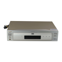
Photo: DVP-NS905V (Silver type)
System
Laser: Semiconductor laser
Signal format system:
DVP-NS755V: NTSC
DVP-NS915V: NTSC/PAL (To change the
color system)
Audio characteristics
Frequency response: DVD VIDEO (PCM
96 kHz): 2 Hz to 44 kHz (44 kHz: –2 dB
±1 dB)/Super Audio CD: 2 Hz to
100 kHz (50 kHz: –3 dB ±1dB)/CD:
2Hz to 20 kHz (±0.5 dB)
Signal-to-noise ratio (S/N ratio): 115 dB
(LINE OUT L/R (AUDIO) 1/2 jacks
only
(LINE OUT L/R (AUDIO) jacks only)
(AEP, UK, Russian)
) (EXCEPT AEP, UK, Russian)
Harmonic distortion: 0.003 %
Dynamic range: DVD VIDEO/Super Audio
CD: 103 dB/CD: 99 dB
Wow and flutter: Less than detected value
(±0.001% W PEAK)
(Jack name: Jack type/Output level/Load
impedance)
LINE OUT (AUDIO) 1/2: Phono jack/
2Vrms/10 kilohms
DIGITAL OUT (OPTICAL): Optical
output jack/–18 dBm (wave length:
660 nm)
DIGITAL OUT (COAXIAL): Phono jack/
0.5 Vp-p/75 ohms
5.1CH OUTPUT: Phono jack/2 Vrms/
10 kilohms
COMPONENT VIDEO OUT(Y, P
B/CB, PR/
C
R): Phono jack/Y: 1.0 Vp-p/PB/CB, PR/
CR: 0.7 Vp-p/75 ohms
LINE OUT (VIDEO) 1/2: Phono jack/
1.0 Vp-p/75 ohms
S VIDEO OUT 1/2: 4-pin mini DIN/Y:
1.0 Vp-p, C: 0.3 Vp-p (PAL), 0.286 Vp-p
(NTSC)/75 ohms
General
Power requirements:
110 V AC, 60 Hz
120 V AC, 60 Hz
220 V AC, 60 Hz
22
110–240 V AC, 50/60 Hz
0–240 V AC, 50/60 Hz
See page 1-1 for further information
Power consumption:
15 W
16 W
17
18 W
W
See page 1-1 for further information
Mass (approx.):
DVP-NS705V/NS755V:
2.6 kg (5
47
/
64
lb)
DVP-NS905V/NS915V:
2.8 kg (6
3
/
16
lb)
Operating temperature: 5 ° C to 35 ° C
(41
°
F to 95
°
F)
Operating humidity: 25 % to 80 %
Supplied accessories
Specifications and design are subject to
change without notice.
ENERGY STAR
R
is a U.S. registered mark.
As an
ENERGY STAR
R
Partner, Sony
Corporation has determined that this product
meets the
ENERGY STAR
R
guidelines for
energy efficiency.
DVP-NS705V/NS905V: PAL (NTSC)
Outputs
(
AEP, UK, Russian:
EXCEPT AEP, UK, Russian:
Jack name: Jack type/Output level/Load
impedance)
LINE OUT (AUDIO): Phono jack/2 Vrms/
10 kilohms
DIGITAL OUT (OPTICAL): Optical
output jack/–18 dBm (wave length:
660 nm)
DIGITAL OUT (COAXIAL): Phono jack/
0.5 Vp-p/75 ohms
5.1CH OUTPUT: Phono jack/2 Vrms/
10 kilohms
LINE OUT (VIDEO): Phono jack/1.0 Vp-p/
75 ohms
S VIDEO OUT: 4-pin mini DIN/Y: 1.0
Vp-p, C: 0.3 Vp-p (PAL), 0.286 Vp-p
(
NTSC
)
/75 ohms
Check that you have the following items:
•Audio/video cord (pinplug × 3 y pinplug
× 3) (1)
•Remote commander (remote) (1)
•Size AA (R6) batteries (2)
Dimensions (approx.):
DVP-NS705V/NS755V:
430 × 74 × 257 mm (17 × 3 × 10
1
/
8
in.)
DVP-NS905V/NS915V:
430 × 77 × 257 mm (17 × 3
1
/
8
× 10
1
/
8
in.) (width/height/depth) incl. projecting
parts

Table of Contents

Questions and Answers:

Sony RMT-D147P Specifications

General IconGeneral
TypeRemote Control
BrandSony
ModelRMT-D147P
Compatible DevicesSony DVD Players
ConnectivityInfrared (IR)

Summary

SPECIFICATIONS

System

Details about the laser, signal format, and audio characteristics of the player.

Audio Characteristics

Frequency response, signal-to-noise ratio, dynamic range, and harmonic distortion.

Outputs

Technical specifications for various audio and video output connectors.

General

Power requirements, power consumption, operating temperature, and humidity.

Supplied Accessories

List of items included with the product.

Safety Check-Out Procedure

Leakage Test

Procedure to check AC leakage from exposed metal parts to earth ground.

Unleaded Solder Characteristics

Information on the properties and handling of unleaded solder.

Service Notes and Disassembly

Service Note

General notes and precautions for servicing the unit.

Disassembly Procedure Overview

Step-by-step guide for disassembling the player unit.

Disc Handling and Servicing

Disc Removal Procedure

Steps to safely remove a disc from the player.

Servicing the MB-105 Board

Instructions for accessing and servicing the MB-105 circuit board.

General Information and Precautions

General Precautions

Safety and operational guidelines for using the player.

Important Safety Notice

Warning about potential damage to television screens from static images.

Disc Compatibility

List of disc types that the player cannot play.

Disc Handling Notes

Recommendations for keeping discs clean and storing them.

Controls and Indicators

Index to Parts and Controls

Reference guide to the player's buttons, indicators, and ports.

Front Panel Controls

Identification and function of buttons on the front panel.

Front Panel Display Indicators

Explanation of symbols and messages on the front display.

Rear Panel Connections

Identification of all input and output connectors on the rear panel.

Remote Control Layout

Diagram and description of the remote control buttons.

Navigating the Player Interface

Control Menu Display Guide

How to use the Control Menu to select functions and view information.

Control Menu Item List

Detailed list of available items within the Control Menu.

Simple Start Guide Overview

Basic steps to get the player set up and running quickly.

Step 1: Unpacking the Player

Instructions for unpacking the player and checking contents.

Step 2: Inserting Remote Batteries

Guidance on installing batteries into the remote control.

Initial Setup and Connections

Step 3: TV Hookups

Instructions for connecting the player to a television.

Aspect Ratio Adjustment

How to adjust the aspect ratio for different TV screen types.

Color System Adjustment

How to change the player's color system setting (DVP-NS915V only).

Hooking Up the Player

General steps for connecting all components.

Connecting Video Cords

Detailed guide for connecting video cables to various devices.

Audio and Video Connectivity

Video Connection Options

Details on connecting via video input, S-VIDEO, and component video.

Audio Cord Connections

Guide to connecting audio cords for various audio systems.

Audio System Connections

Stereo Amplifier/MD Deck Connections

Connecting to stereo amplifiers, MD, or DAT decks.

Dolby Surround AV Receiver Connections

Connecting to AV receivers with Dolby Surround decoders.

5.1 Channel AV Receiver Connections

Connecting to AV receivers with 5.1 channel or digital inputs.

Connecting to 5.1ch Input Jacks

Details for connecting to 5.1 channel audio inputs.

Connecting to Digital Jack

Details for connecting to digital audio outputs.

Initial Setup and Playback Features

Connecting the Power Cord

Instructions for connecting the player and TV to the power outlet.

Quick Setup Guide

Step-by-step initial configuration for optimal performance.

Enjoying Surround Sound Effects

Guidance on configuring audio settings for surround sound.

Basic Disc Playback Operations

Playing Discs

Standard procedures for playing DVDs, CDs, and other disc types.

Additional Operations

Extended functions available during playback.

Disc Tray Child Lock

How to lock and unlock the disc tray to prevent unauthorized access.

Disc Navigation and Playback Modes

Searching for a Disc Point

Methods for finding specific points on a disc: Search, Scan, Slow-motion, Freeze Frame.

Using the Click Shuttle

Operating the shuttle control for various playback speeds and modes.

Frame-by-Frame Playback with Click Shuttle

Using the click shuttle for precise frame-by-frame playback.

Advanced Playback Functions

Resuming Playback

How to resume playback from where you last stopped a disc.

Using DVD Menus

Navigating DVD titles, scenes, and interactive menus.

DVD-RW Title Selection

Choosing between 'ORIGINAL' and 'PLAY LIST' titles on DVD-RW discs.

Super Audio CD Playback Options

Selecting playback areas (2-channel or multi-channel) on SACDs.

Hybrid SACD Layer Selection

Choosing playback layer (HD or CD) on hybrid SACDs.

VIDEO CD PBC Playback

Interactively playing VIDEO CDs using Playback Control (PBC).

Program Play and Search Functions

Program Play Management

Creating, changing, and canceling playback programs.

Shuffle Play Mode

Playing tracks, chapters, or titles in a random order.

Repeat Play Modes

Repeating entire discs, titles, chapters, or tracks.

A-B Repeat Play

Repeating a specific segment of audio or video.

Scene Search Modes

Searching for titles, chapters, tracks, scenes, or time codes.

Disc Information and Playback Details

Scene Search and Picture Navigation

Finding scenes quickly using picture navigation features.

Scanning Titles, Chapters, or Tracks

Viewing first scenes of titles, chapters, or tracks in subscreens.

Displaying Multiple Angles

Viewing different angles of a scene simultaneously.

Dividing Scene into Sections

Displaying 9 consecutive moving pictures for strobe playback.

Checking Playing Time and Remaining Time

Viewing playback duration and remaining time for discs.

Displaying Disc Text Information

Accessing text data like track names or album titles from discs.

Front Panel Display Information

Checking playback information shown on the front panel display.

Disc Information and Sound Adjustments

Checking Play Information

Viewing bit rate, layer information, and other disc playback details.

DVD Advanced Playback Information

Detailed information for DVDs, including bit rate and layer.

Data CD Playback Information

Information specific to DATA CDs, such as audio bit rate.

Sound Adjustments Overview

General section for configuring audio settings.

Changing Sound Modes

Selecting different audio formats and languages for DVDs.

Displaying Disc Audio Information

Viewing details about the current audio format and channels.

Movie Playback Features

Surround Sound Mode Settings

Selecting surround sound modes for various speaker setups.

Changing Viewing Angles

Switching between multiple angles recorded on DVD VIDEOs.

Subtitle Display Options

Turning subtitles on/off and changing subtitle languages.

Picture Quality Adjustments

Adjusting Picture Quality (BNR)

Reducing block noise and mosaic patterns in the picture.

Customizing Playback Picture

Adjusting picture elements like brightness, color, and contrast.

Adjusting Picture Items in Memory

Detailed adjustment of picture settings within the MEMORY mode.

Enhancing Playback Picture (DVE)

Improving picture clarity by enhancing outlines or softening images.

Additional Functions and Controls

Disc Locking Features

Setting parental controls to restrict playback of certain discs.

Parental Control Setup

Configuring playback limitations based on age or region.

Password Management

Setting, changing, or turning off parental control passwords.

System Operations and Remote Control

Sound Feedback Settings

Configuring operational sound effects (beeps) for player actions.

Controlling TV with Remote

Setting up the remote to control basic TV functions.

Controlling AV Receiver Volume

Using the remote to adjust the volume of an AV amplifier.

System Setup and Adjustments

Using the Setup Display

Navigating the on-screen display for system adjustments.

Language Settings

Selecting languages for OSD, menus, audio, and subtitles.

Display Settings

Configuring TV type, screen saver, background, and component output.

System and Audio Settings

Custom Settings (CUSTOM SETUP)

Configuring playback and other system settings.

Sound Settings (AUDIO SETUP)

Adjusting audio output based on playback and connection.

Speaker Setup and Troubleshooting

Speaker Setup Configuration

Setting speaker size, distance, balance, and level for optimal surround sound.

Troubleshooting Common Issues

Guidance for resolving power, picture, and sound problems.

Troubleshooting and Glossary

Additional Information and Troubleshooting

Resolving issues related to surround effects, remote function, and disc playback.

Self-Diagnosis Function

Understanding and using the player's self-diagnosis feature.

Glossary of Terms

Definitions of technical terms used in the manual.

Glossary and Language Codes

Glossary of Technical Terms

Definitions for terms like Chapter, Dolby Digital, DTS, DVD VIDEO, etc.

Language Code List

List of language codes used for audio and subtitle selection.

Disassembly Procedures

Section 2: Disassembly Overview

General instructions for disassembling the player unit.

Case Removal

Step-by-step instructions for removing the player's outer case.

Tray Cover Assembly Removal

Procedure for removing the tray cover assembly.

Front Panel Block Assembly Removal

Instructions for removing the front panel assembly.

Power Block Removal

Procedure for removing the power supply block.

Disassembly Procedures Continued

Mechanism Deck Removal

Steps to remove the disc mechanism deck.

AV-64 Board Removal

Procedure for removing the AV-64 circuit board.

MB-105 Board Removal

Steps to remove the MB-105 circuit board.

ER-19 Board Removal

Procedure for removing the ER-19 circuit board.

Disassembly Procedures for Boards

IF-94 Board Removal

Instructions for removing the IF-94 circuit board.

Optical Pick-up Removal

Procedure for removing the optical pick-up assembly.

Internal Views and Board Locations

Internal Views of Mechanism

Visual inspection of the disc mechanism and optical pick-up.

Circuit Board Locations

Circuit Board Locations Diagram

Diagram showing the placement of major circuit boards within the player.

Block Diagrams Overview

Section 3: Block Diagrams

Overview of the player's system architecture through block diagrams.

Overall Block Diagram

High-level block diagram of the entire player system.

RF and Servo System Block Diagram

RF/Servo Block Diagram

Detailed block diagram of the RF amplifier and servo control systems.

Signal Processing Block Diagram

Signal Processor Block Diagram

Block diagram illustrating the signal processing functions.

System Control Block Diagram

System Control Block Diagram

Block diagram showing the system control operations.

Video System Block Diagrams

Video (1) Block Diagram

Block diagram detailing the first part of the video processing system.

Video System Block Diagrams Continued

Video (2) Block Diagram

Block diagram detailing the second part of the video processing system.

Audio System Block Diagrams

Audio (1) Block Diagram

Block diagram illustrating the first stage of audio processing.

Audio System Block Diagrams Continued

Audio (2) Block Diagram

Block diagram illustrating the second stage of audio processing.

Interface Control Block Diagram

Interface Control Block Diagram

Block diagram showing the interface control functions.

Power Supply Block Diagrams

Power (1) Block Diagram

Block diagram of the power supply system, part 1.

Power Supply Block Diagrams Continued

Power (2) Block Diagram

Block diagram of the power supply system, part 2.

Printed Wiring Boards and Schematics

Section 4: Printed Wiring Boards and Schematic Diagrams

Overview of circuit diagrams and board layouts.

Notes for Diagrams

Important notes regarding printed wiring boards and schematic diagrams.

Frame Schematic Diagram

Frame Schematic Diagram

Overall schematic diagram illustrating the system connections.

Board and Schematic Diagrams

Printed Wiring Boards and Schematic Diagrams

Index for specific board diagrams and their corresponding schematics.

MS-81 (Loading) Board Diagram

Printed wiring board and schematic for the MS-81 loading mechanism.

MB-105 Board Diagrams

MB-105 (Signal Process, Servo) Printed Wiring Board

Printed wiring board layout for the MB-105 board.

MB-105 Board Layout

MB-105 Board (Side B) Layout

Component layout on the reverse side (Side B) of the MB-105 board.

MB-105 Schematics - RF Amp and Servo

MB-105 (RF AMP, SERVO) Schematic Diagram

Schematic diagram for the RF amplifier and servo systems on the MB-105 board.

MB-105 Schematics - ARP, Servo DSP

ARP, SERVO DSP MB-105 (2/11)

Schematic diagram for the ARP and Servo DSP functions on the MB-105 board.

MB-105 Schematics - AV Decoder

AV DECODER MB-105 (3/11)

Schematic diagram for the AV Decoder section on the MB-105 board.

MB-105 Schematics - Motor Drive

MOTOR DRIVE MB-105 (4/11)

Schematic diagram for the motor drive circuits on the MB-105 board.

MB-105 Schematics - System Control

SYSTEM CONTROL MB-105 (5/11)

Schematic diagram for the system control unit on the MB-105 board.

MB-105 Schematics - Clock Generator

CLOCK GENERATOR MB-105 (6/11)

Schematic diagram for the clock generator circuit on the MB-105 board.

MB-105 Schematics - I/P Converter

I/P CONVERTER MB-105 (7/11)

Schematic diagram for the input/output converter on the MB-105 board.

MB-105 Schematics - Video Encoder

VIDEO ENCODER, AUDIO D/A CONVERTER MB-105 (8/11)

Schematic diagram for video encoder and audio DAC on MB-105 board.

MB-105 Schematics - Audio DSP

AUDIO DSP MB-105 (9/11)

Schematic diagram for the audio DSP unit on the MB-105 board.

MB-105 Schematics - 2ch/6ch DAC

2ch/6ch DAC MB-105 (10/11)

Schematic diagram for the 2-channel and 6-channel DAC on the MB-105 board.

MB-105 Schematics - SACD Decoder

SACD DECODER MB-105 (11/11)

Schematic diagram for the SACD decoder on the MB-105 board.

LED Board Diagram

LED LE-34

Printed wiring board and schematic for the LE-34 LED board.

AV-64 Board Diagrams

AUDIO/VIDEO OUT AV-64

Printed wiring board layout for the AV-64 board.

AV-64 Board Layout

AV-64 BOARD (SIDE B)

Component layout on the reverse side (Side B) of the AV-64 board.

AV-64 Schematics - Video Buffer

VIDEO BUFFER AV-64 (1/3)

Schematic diagram for the video buffer circuit on the AV-64 board.

AV-64 Schematics - Audio Amp

AUDIO AMP AV-64 (2/3)

Schematic diagram for the audio amplifier circuit on the AV-64 board.

AV-64 Schematics - 5.1ch Audio Amp

5.1CH AUDIO AMP AV-64 (3/3)

Schematic diagram for the 5.1 channel audio amplifier on the AV-64 board.

IF-94 Board Diagrams

INTERFACE CONTROL IF-94

Printed wiring board layout for the IF-94 interface control board.

IF-94 Board Layout

IF-94 BOARD (SIDE B)

Component layout on the reverse side (Side B) of the IF-94 board.

IF-94 Schematics - IF CON

IF CON IF-94

Schematic diagram for the IF CON circuit on the IF-94 board.

ER-19 Board Diagrams

EURO AV ER-19

Printed wiring board layout for the ER-19 EURO AV board.

ER-19 Schematics - EURO AV

EURO AV ER-19

Schematic diagram for the EURO AV interface on the ER-19 board.

Switching Regulator ETXNY393N2F Diagrams

ETXNY393N2F (Switching Regulator) Printed Wiring Board

Printed wiring board layout for the ETXNY393N2F switching regulator.

Switching Regulator ETXNY393N2F Schematics

ETXNY393N2F (Switching Regulator) Schematic Diagram

Schematic diagram for the ETXNY393N2F switching regulator circuit.

Switching Regulator HS12S1U Diagrams

HS12S1U (Switching Regulator) Printed Wiring Board

Printed wiring board layout for the HS12S1U switching regulator.

Switching Regulator HS12S1U Schematics

HS12S1U (Switching Regulator) Schematic Diagram

Schematic diagram for the HS12S1U switching regulator circuit.

Switching Regulator HS12S1F Diagrams

HS12S1F (Switching Regulator) Printed Wiring Board

Printed wiring board layout for the HS12S1F switching regulator.

Switching Regulator HS12S1F Schematics

HS12S1F (Switching Regulator) Schematic Diagram

Schematic diagram for the HS12S1F switching regulator circuit.

IC Pin Function Descriptions

Section 5: IC Pin Function Description

Detailed pin functions for integrated circuits used in the player.

System Control IC Pin Functions (MB-105 IC104)

Pinout and function description for the system control IC.

Test Mode Operations

Section 6: Test Mode

Procedures for diagnosing and adjusting the player.

General Description of Test Mode

Overview of the test mode functions and usage.

Starting Test Mode

Instructions for entering the player's test mode.

Power Off Information Codes

List of codes indicating the cause of the last power off.

Syscon Diagnosis Menu

Navigating the system control diagnosis menu.

Diagnostic Submenus and Checks

Submenu Navigation

How to select and navigate through diagnostic submenus.

Version Information Checks

Checking ROM revision, ROM checksum, model type, and region.

Peripheral Component Checks

Tests for EEPROM, SACD, Venc, and external RAM.

Servo System Checks

Tests for Servo DSP, function support, and RF amplifier.

Power Supply Checks

Tests related to ARP register and RAM bus.

AV Decoder Checks

Tests for 1935 RAM and 1935 SP functions.

Diagnostic Checks - Supply and AV Decoder

Supply Checks (ARP)

Detailed checks for ARP register, RAM data bus, address bus, and RAM.

AV Decoder Checks

Checks for 1935 RAM and 1935 SP functions.

Diagnostic Checks - Video and Audio

Video System Checks

Checks for Color Bar, Composite, Y/C, RGB, Component outputs, and Euro AV.

Audio System Checks

Checks for ARP to 1935, and Test Tone output.

Diagnostic Check Items List

Comprehensive list of all diagnostic checks available.

Error Codes List

Drive Adjustment Procedures

6-4. Drive Auto Adjustment

Procedure for automatically adjusting the disc drive system.

DVD-SL (Single Layer) Adjustment

Steps for adjusting single-layer DVD discs.

All Items Auto Adjustment

Option to perform automatic adjustment for all disc types.

Drive Adjustment Procedures Continued

CD Adjustment Steps

Steps for adjusting CD discs.

DVD-DL (Dual Layer) Adjustment Steps

Steps for adjusting dual-layer DVD discs.

LCD (SACD) Adjustment Note

Note regarding adjustments for LCD and SACD discs.

Manual Drive Operation

6-5. Drive Manual Operation

Procedure for manually controlling servo and adjustment.

Disc Check Memory

Checking disc memory and resetting SLED TILT.

Disc Type Selection

Selecting the correct disc type for manual operation.

Servo Control and Track/Layer Jump

Servo Control Functions

Controlling servo operations like LD, SP, Focus, TRK, Sled, CLVA.

Track/Layer Jump Functions

Performing track and layer jumps for DVD-DL discs.

Manual and Automatic Adjustments

Manual Adjustment Parameters

Adjusting parameters like TRK Offset, Focus Gain, and EQ Boost manually.

Auto Adjustment Options

Performing automatic adjustments for tracking, focus, and EQ.

Memory Check

Viewing stored adjustment data in EEPROM.

Memory Check and Special Tests

EEPROM Data Display

Viewing stored adjustment data from EEPROM.

Mecha Aging Test

Procedure for aging the mechanism by repeating operations.

Emergency History Log

Accessing and clearing the player's emergency history.

Version Information and Self-Diagnostics

Version Information Display

Checking the player's firmware version, model, and region.

Video Level Adjustment

Procedure for adjusting the video level using color bars.

IF CON Self-Diagnostic Function

Diagnosing IF CON and front panel board functions.

IF-94 Board Test Mode

Testing button, remote, communication, and LED functions.

Self Check Mode Operation

Conducting basic tests on the FL display and DVD panel.

Troubleshooting Test Mode Issues

Auto Self Check Operation

How the auto self-check sequence operates and displays information.

MODEL Display in Self Check

Displaying the model information during auto self-check.

Version Display in Self Check

Displaying version information during auto self-check.

ROM Creation Date Display

Displaying ROM creation date during auto self-check.

Self Check Function Details

Each Self Check Functionality

Overview of tests for FLD, LED, and key input.

FLD and LED All ON Test

Testing all segments of the FLD and all LEDs.

Main Unit Key Input Display

Displaying key names and codes pressed on the main unit.

Remote Key Input and Communication Monitoring

Remote Commander Key Input Display

Displaying key names and codes pressed on the remote commander.

Communication Monitoring Display

Monitoring communication status between units.

Self Check Mode Display Tests

FLD Anode Test and Shuttle Click

Testing FLD segments and using shuttle for anode test.

Communication Error Display

Displaying errors during communication monitoring.

Self Check Mode Display Tests Continued

FLD Grid Test and Shuttle Click

Testing FLD grids and using shuttle for grid test.

LED Test Display

Testing the function of all LEDs.

Beep Sound Test

Testing the beep sound output for key presses.

Anode Connection Diagram

Anode Connection Table

Table detailing anode connections for various signals.

Troubleshooting Test Mode Issues Continued

Cannot Enter Test Mode

Troubleshooting steps for failing to enter test mode.

MB-105 Board Test Mode Faults

Diagnosing issues when the test mode menu is not displayed.

Board Visual Check

Checking ICs, pins, and soldering for normal appearance.

Power Supply Voltage Check

Verifying power supply voltages at key points.

Clock Signal Check

Checking clock signals at CPUCK and other related signals.

Troubleshooting Test Mode Issues Further

33 MHz Clock Signal Check

Troubleshooting issues when the 33 MHz signal appears at CPUCK.

AVD (IC403) Check

Checking AVD IC for signal output and potential defects.

INT Signal Check

Checking INT signals for proper voltage levels and connections.

CS Signal Check

Checking CS signals for abnormalities when abnormalities are not confirmed.

SDSP No Ack Message Troubleshooting

Resolving issues when 'SDSP No Ack' message appears.

Picture and Audio Output Issues

Troubleshooting scenarios with no picture, no audio, or only one output.

Troubleshooting Common Player Issues

Drive Auto Adjustment Errors

Troubleshooting drive auto adjustment failures due to circuit errors.

Product Defects

Identifying potential product-level defects if MB-105 is functional.

Power LED Issues

Troubleshooting power LED not lighting correctly.

IF Board Fuse Check

Checking if the fuse on the IF board has blown.

Power Button and P-CONT Check

Checking P-CONT signal related to power button function.

Button Depression Check

Checking for depressed buttons in IF CON self mode.

PONCHK Check on IF-94 Board

Checking the PONCHK signal for IF CON.

FL Display Not Lighting

Troubleshooting FL display issues when power LED is green.

No Picture or Audio Output

Resolving issues where both picture and audio are absent.

Picture Abnormalities

Troubleshooting abnormal picture conditions like block noise.

Electrical Adjustments Section

Section 7: Electrical Adjustment

Procedures for adjusting the player's electrical circuits.

Power Supply Voltage Check

Verifying voltages from the power supply block against specifications.

Required Instruments

List of tools and equipment needed for adjustments.

Abbreviation List

Glossary of abbreviations used in the manual.

Video System Adjustment Procedures

Video Level Adjustment (MB-105)

Adjusting video brightness to meet NTSC standards.

Progressive Video Output Level Adjustment

Adjusting progressive video output for correct brightness.

S-Video Output S-Y Check

Checking S-Video output for correct Y signal level.

S-Video Output S-C Check

Checking S-Video output for correct color information (S-C burst).

Component Video Output Adjustments

Component Video Output Y Check

Verifying the Y component signal level for brightness.

Component Video Output B-Y Check

Verifying the B-Y component signal level for color accuracy.

Component Video Output R-Y Check

Verifying the R-Y component signal level for color accuracy.

Adjustment Parts Location

Adjustment Related Parts Arrangement

Diagram showing locations of parts for adjustment.

MB-105 Board (Side A) Parts Layout

Location of adjustment components on the MB-105 board.

Power Board (Side A) Parts Layout

Location of adjustment components on power boards.

Repair Parts List Section

Section 8: Repair Parts List

List of all replaceable parts for the player.

Notes for Parts List

Important notes regarding part identification and availability.

Exploded Views of Components

Visual breakdown of the player's assemblies and parts.

Front Panel Assembly (NS705V/NS755V)

Exploded view of the front panel assembly for specific models.

Exploded Views of Front Panel and Chassis

Front Panel Assembly (NS905V/NS915V)

Exploded view of the front panel assembly for specific models.

Chassis Assembly (NS705V/NS755V)

Exploded view of the chassis assembly for specific models.

Exploded Views of Chassis and Mechanism

Chassis Assembly (NS705V/NS755V) Continued

Exploded view of the chassis assembly, continuing from previous page.

Chassis Assembly (NS905V/NS915V)

Exploded view of the chassis assembly for specific models.

Exploded Views of Chassis and Mechanism Continued

Chassis Assembly (NS905V/NS915V) Continued

Exploded view of the chassis assembly, continuing from previous page.

Mechanism Deck Assembly

Exploded view of the disc mechanism deck assembly.

Mechanism Deck Assembly Details

Mechanism Deck Assembly Details

Detailed breakdown of parts within the mechanism deck assembly.

AV-64 Board Electrical Parts List

8-2. Electrical Parts List

Comprehensive list of electrical components for the AV-64 board.

Notes for Electrical Parts

Important notes regarding component standardization and stocking.

AV-64 Board Components - Capacitors

AV-64 Board Capacitors

List of capacitors used on the AV-64 board with their specifications.

AV-64 Board Components - Diodes and Connectors

AV-64 Board Diodes and Connectors

List of diodes and connectors used on the AV-64 board.

AV-64 Board Components - Transistors and Resistors

AV-64 Board Transistors

List of transistors used on the AV-64 board.

AV-64 Board Resistors

List of resistors used on the AV-64 board.

ER-19 and IF-94 Board Parts

ER-19 and IF-94 Board Parts List

List of components for the ER-19 and IF-94 boards.

MB-105 Board Components - Resistors

MB-105 Board Resistors

List of resistors used on the MB-105 board.

MB-105 Board Components - Resistors Continued

MB-105 Board Resistors Continued

Continuation of the resistor list for the MB-105 board.

MB-105 Board Components - Resistors Continued

MB-105 Board Resistors Continued

Further continuation of the resistor list for the MB-105 board.

MB-105 Board Components - Resistors Continued

MB-105 Board Resistors Continued

Further continuation of the resistor list for the MB-105 board.

MB-105 Board Components - Resistors Continued

MB-105 Board Resistors Continued

Further continuation of the resistor list for the MB-105 board.

MB-105 Board Components - Resistors Continued

MB-105 Board Resistors Continued

Further continuation of the resistor list for the MB-105 board.

MB-105 Board Components - Resistors Continued

MB-105 Board Resistors Continued

Further continuation of the resistor list for the MB-105 board.

MB-105 Board Components - Resistors Continued

MB-105 Board Resistors Continued

Further continuation of the resistor list for the MB-105 board.

MB-105 Board Components - Resistors Continued

MB-105 Board Resistors Continued

Final continuation of the resistor list for the MB-105 board.

Power Supply Block Parts List

Power Supply Block (HS12S1U) Parts

List of parts for the HS12S1U power supply block.

Related product manuals