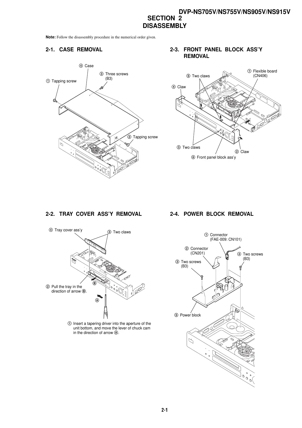
2-1
Note: Follow the disassembly procedure in the numerical order given.
2-1. CASE REMOVAL
SECTION 2
DISASSEMBLY
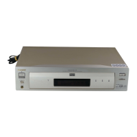
DVP-NS705V/NS755V/NS905V/NS915V
1 Tapping screw
2 Tapping screw
3 Three screws
(B3)
4 Case
2 Pull the tray in the
direction of arrow B.
3 Two claws
4 Tray cover ass’y
1 Insert a tapering driver into the aperture of the
unit bottom, and move the lever of chuck cam
in the direction of arrow A.
B
A
2 Claw
4 Claw
3 Two claws
5 Two claws
1 Flexible board
(CN406)
6 Front panel block ass’y