7-2
DVP-NS611HP/NS710H/NS710HP/NS717HP/NS718H/NS718HP/NS728H/NS728HP
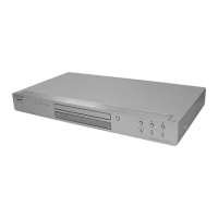
3. Checking RGB Output G (RGB Mode)
(Europe Model)
<Purpose>
This checks RGB video output G level. If it is incorrect, correct color
will not be remain some.
Mode HLX-504 play back
Signal Color bars
Test point Green Out (11p) (75 Ω terminated)
Instrument Oscilloscope
Specification A = 700 ± 70mVp-p
Checking method:
(1) In the Video Signal menu “1” Color Bar 100% play back.
(2) Confirm that the G level is A.
Fig. 7-3.
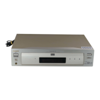
4. Checking RGB Output B (RGB Mode)
(Europe Model)
<Purpose>
This checks RGB video output B level. If it is incorrect, correct
colors will not be displayed when connected to, for instance,
projector.
Mode HLX-504 play back
Signal Color bars
Test point Blue Out, (7p) (75 Ω terminated)
Instrument Oscilloscope
Specification A = 700 ± 70 mVp-p
Checking method:
(1) In the Video Signal menu “1” Color Bar 100% play back.
(2) Confirm that the B level is A.
Fig. 7-4.
A
A
7-2. ADJUSTMENT OF VIDEO SYSTEM
Euro Model
(DVP-NS718H:AEP,UK,RUS/
NS728H:AEP,UK,RUS)
1. Checking Video Level
<Purpose>
Checking Video Level the NTSC/PAL standard, and if not correct,
the brightness will be too large or small.
Mode HLX-504 play back
Signal Color bars 100%
Test point LINE OUT (VIDEO) connector
(75 Ω terminated)
Instrument Oscilloscope
Specification 1.0 ± 0.08 Vp-p
Adjusting method:
(1) In the Video Signal menu “1” Color Bar 100% play back.
(2) Confirm that the Video Level is 1.0 ± 0.08 Vp-p.
Fig. 7-1.
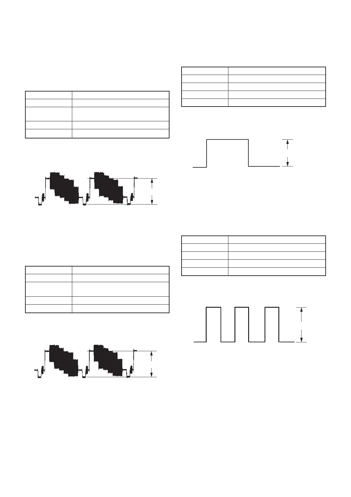
2. Checking Scart Video Output Level (Video
Mode) (Euro Model)
<Purpose>
Check scart video output level. If it is incorrect, correct brightness
will be too large or small.
Mode HLX-504 play back
Signal Color bars 100%
Test point VIDEO OUT (19p)
connector (75 W terminated)
Instrument Oscilloscope
Specification 1.0 ± 0.08 Vp-p
Adjusting method:
(1) In the Video Signal menu “1” Color Bar 100% play back.
(2) Confirm that the video level is 1.0 ± 0.08 Vp-p.
Fig. 7-2.
1.0 ± 0.08 Vp-p
1.0 ± 0.08 Vp-p