5-4
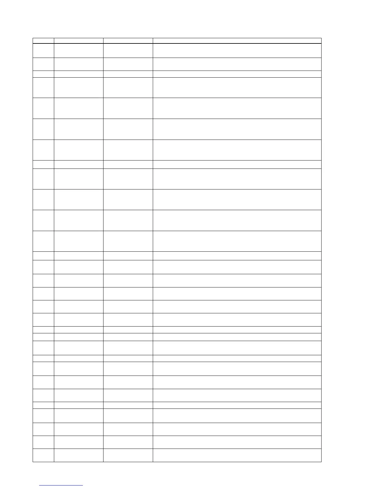
Pin No. Pin name Type Function
90 RCS# Output DRAM chip select, active low
2~16MA, SR
91 BA0 Output DRAM bank address 0
2~16MA, SR
92 DVSS Ground Ground pin for internal digital circuitry
93 RD15 Inout DRAM data 15
2~16MA, SR
PU/PD, SMT
94 RD14 Inout DRAM data 14
2~16MA, SR
PU/PD, SMT
95 RD13 Inout DRAM data 13
2~16MA, SR
PU/PD, SMT
96 RD12 Inout DRAM data12
2~16MA, SR
PU/PD, SMT
97 DVDD3 Power 3.3V power pin for internal digital circuitry
98 RD11 Inout DRAM data 11
2~16MA, SR
PU/PD, SMT
99 RD10 Inout DRAM data 10
2~16MA, SR
PU/PD, SMT
100 RD9 Inout DRAM data 9
2~16MA, SR
PU/PD, SMT
101 RD8 Inout DRAM data 8
2~16MA, SR
PU/PD, SMT
102 DVSS Ground Ground pin for internal digital circuitry
103 CLK Output DRAM clock
2~16MA, SR
104 CLE Output DRAM clock enable
2~16MA, SR
105 RA11 Output DRAM address bit 11 or audio serial data 3 (channel 7/8)
2~16MA, SR
106 RA9 Output DRAM address 9
2~16MA, SR
107 RA8 Output DRAM address 8
2~16MA, SR
108 DMVDD3 Power 3.3V Power pin for DRAM clock circuitry
109 DMVSS Ground Ground pin for DRAM clock circuitry
110 RA7 Output DRAM address 7
2~16MA, SR
111 DVDD3 Power 3.3V power pin for internal digital circuitry
112 RA6 Output DRAM address 6
2~16MA, SR
113 RA5 Output DRAM address 5
2~16MA, SR
114 RA4 Output DRAM address 4
2~16MA, SR
115 DVSS Ground Ground pin for internal digital circuitry
116 DQM1 Output Mask for DRAM input/output byte 1
2~16MA, SR
117 DQM0 Output Mask for DRAM input/output byte 0
2~16MA, SR
118 BA1 Output DRAM bank address 0
2~16MA, SR
119 RA10 Output DRAM address 10
2~16MA, SR