HT-CT380/CT381
12
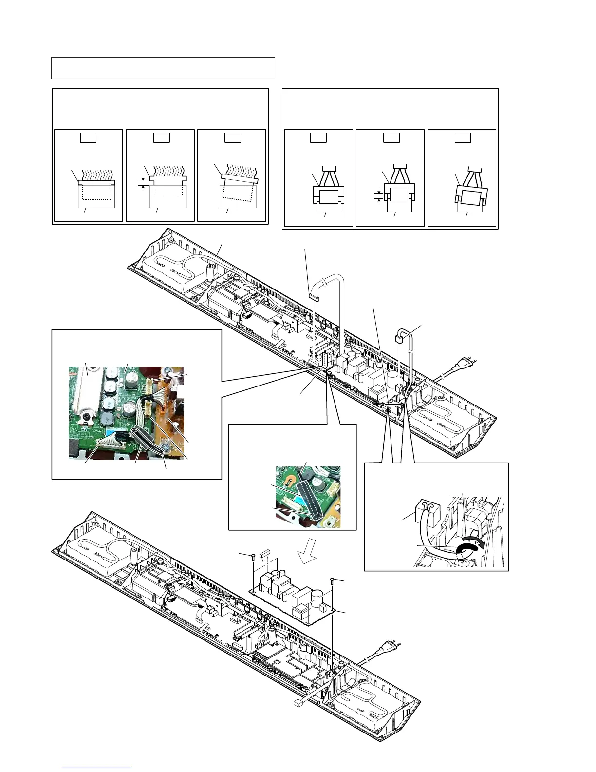
2-6. POWER BOARD
3RZHUFRUGVHWWLQJ
wiring stopper
Dress the wiring stopper
toward the arrow direction.
CN901
6 POWER board
5 two screws
(BV3)
5 two screws
(BV3)
1 Remove the wire
from the wiring stopper
with cushion (CZ2-A).
3 Remove the power cord
from the wiring stopper.
4 power cord connector
(CN901)
cabinet (bottom) block
Insert only part way.Insert straight into
the interior.
connector
Insert at a slant.
connector
connector
connector
connector connector
OK NG NG
+RZWRLQVWDOOWKHFRQQHFWRU
Insert the connector straight into the interior.
There is a possibility that using this unit without
the connector correctly installed will damage it.
:LUHVHWWLQJ
Note 3:
Do not pass the wire close to the heat sink.
MAIN board
CN1005
wiring stopper
cushion (CZ2-A)
CN3002
CN3005
heat sink
heat sink
2 connector (CN1005)
Note 2:
Before connect this connector, refer to “CAPACITOR
ELECTRICAL DISCHARGE PROCESSING” on page 4.
&XVKLRQ&=$VHWWLQJ
Note 4:
Paste the cushion (CZ2-A) to
screw head and wiring stopper.
wiring stopper
screw head
cushion
(CZ2-A)
Insert only part way.Insert straight into
the interior.
connector
connector
Insert at a slant.
connector connector
connector
connector
OK NG NG
+RZWRLQVWDOOWKHSRZHUFRUGFRQQHFWRU
Insert the connector straight into the interior.
There is a possibility that using this unit without
the connector correctly installed will damage it.
Note 1: When the complete POWER board is replaced, refer to “BOND
FIXATION OF ELECTRIC PARTS” on page 6.