SERVICE MANUAL
Sony Corporation
Published by Sony Techno Create Corporation
HT-CT770
SA-CT770
SPECIFICATIONS
HT-CT770
SOUND BAR
SA-CT770
ACTIVE SPEAKER SYSTEM
9-893-982-02
2014F33-1
©
2014.06
US Model
Canadian Model
AEP Model
UK Model
Australian Model
Chinese Model
Saudi Arabia Model
Singapore Model
Taiwan Model
Ver. 1.1 2014.06
• All of the units included in the HT-CT770 (SA-CT770/
SA-WCT770) are required to confi rming operation of SA-
CT770. Check in advance that you have all of the units.
COMPONENT MODEL NAME
HT-CT770
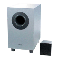
Bar Speaker (Active Speaker System) SA-CT770
Subwoofer (Active Subwoofer) SA-WCT770
Amplifier section
U.S. models:
POWER OUTPUT AND TOTAL HARMONIC DISTORTION:
(FTC)
Front L + Front R:
With 4 ohms loads, both channels driven, from 200 - 20,000 Hz;
rated 35 Watts per channel minimum RMS power, with no more than
1% total harmonic distortion from 250 milliwatts to rated output.
POWER OUTPUT (reference)
Front L/Front R: 105 Watts (per channel at 4 ohms, 1 kHz)
Except US model:
POWER OUTPUT (rated)
Front L + Front R: 50 W + 50 W
(at 4 ohms, 1 kHz, 1% THD)
POWER OUTPUT (reference)
Front L/Front R: 105 Watts (per channel at 4 ohms, 1 kHz)
Inputs
HDMI IN 1/2/3*
ANALOG IN
DIGITAL IN (OPT (TV))
* These 3 jacks are identical. Using any of them makes no difference.
Output
HDMI OUT (TV (ARC))
BLUETOOTH section
Communication system
BLUETOOTH Specification version 3.0
Output
BLUETOOTH Specification Power Class 2
Maximum communication range
Line of sight approx. 10 m (33 ft)
1)
Maximum number of devices to be registered
9 devices
Frequency band
2.4 GHz band (2.4000 GHz - 2.4835 GHz)
Modulation method
FHSS (Freq Hopping Spread Spectrum)
Compatible BLUETOOTH profiles
2)
A2DP (Advanced Audio Distribution Profile)
AVRCP 1.3 (Audio Video Remote Control Profile)
Supported Codecs
3)
SBC
4)
, AAC
5)
Transmission range (A2DP)
20 Hz - 20,000 Hz (Sampling frequency 44.1 kHz)
1) The actual range will vary depending on factors such as obstacles
between devices, magnetic fields around a microwave oven, static
electricity, cordless phone, reception sensitivity, operating system,
software application, etc.
2) BLUETOOTH standard profiles indicate the purpose of BLUETOOTH
communication between devices.
3) Codec: Audio signal compression and conversion format
4) Subband Codec
5) Advanced Audio Coding
Front L/Front R speaker section
Speaker system
2-way speaker system, Acoustic suspension
Speaker
60 mm (2 3/8 in) cone type woofer
20 mm (13/16 in) balance drive tweeter
Rated impedance
4 ohms
General
Power requirements
120 V AC, 60 Hz (US and Canadian models)
220 V - 240 V AC, 50 Hz/60 Hz
(AEP, UK, Australian, Chinese and Singapore models)
110 V - 240 V AC, 50 Hz/60 Hz (Saudi Arabia model)
120 V AC, 50 Hz/60 Hz (Taiwan model)
Power consumption
On: 34 W
Standby mode (Control for HDMI is set to on): 0.5 W or less
Standby mode (Control for HDMI is set to off): 0.3 W or less
BLUETOOTH Standby mode: 0.5 W or less
Dimensions (approx.) (w/h/d)
1030 mm × 50 mm × 113 mm (40 5/8 in × 2 in × 4 1/2 in)
(without wall mountin
g brackets)
1030 mm × 113 mm × 72 mm (40 5/8 in × 4 1/2 in × 2 7/8 in)
(with wall mounting brackets)
Mass (approx.)
2.6 kg (5 Ib 11 3/4 oz)
Speaker system
Wireless Sound Specification version 2.0
Frequency band
2.4 GHz (2.4000 GHz - 2.4835 GHz)
Modulation method
Pi / 4 DQPSK
Digital audio input formats supported by the system
* It is possible to input these formats only with HDMI connection.
Wireless transmitter section
Dolby Digital DTS-HD Master Audio*
Dolby Digital Plus* DTS-HD High Resolution Audio*
Dolby TrueHD* DTS-HD Low Bit Rate*
DTS Linear PCM 2ch 48 kHz or less
DTS 96/24 Linear PCM Maximum 7.1ch 192 kHz or less*
– Continued on next page –