Do you have a question about the Sony SA-NT5 and is the answer not in the manual?
Details of the amplifier circuit, including power output and distortion specifications.
Specifications for the HDMI interface, including connector type and protocol support.
Details on wireless LAN communication system, frequency band, and modulation method.
Specifications for Bluetooth connectivity, including version, profiles, codecs, and range.
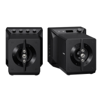
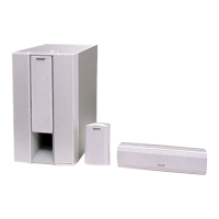
Details of the front speaker system, including speaker type and dimensions.
Overall specifications including power requirements, power consumption, dimensions, and mass.
Lists compatible iPod and iPhone models for use with the system.
Specifications for the wireless transmitter, including communication system and frequency band.
Outlines essential safety checks to perform before releasing the unit to the customer.
Details the procedure and acceptable limits for testing AC leakage current from exposed metal parts.
Details regarding the use and characteristics of unleaded solder for PCB repair.
Notes on preparing for operation checks and safely discharging capacitors.
Guide to identifying different model versions using part and destination codes.
Procedure for writing network information after replacing specific boards.
Steps to verify network connections and inform customers about MAC address changes.
Steps to verify wireless LAN connectivity using a TV monitor and access point.
Steps to verify wired LAN connectivity using a router and LAN cable.
Steps to verify NFC connection by pairing with a mobile device.
Information to provide customers regarding MAC address changes after repair.
Procedure to reset all system settings to the initial factory shipment state.
Procedure to re-establish wireless link between the bar speaker and subwoofer after replacement.
Illustrates the correct bonding procedure for fixed electrical parts.
Advice on preventing touch panel malfunctions by avoiding contact with surfaces.
Instructions for applying thermal compound when replacing ICs on the AMP board.
A flowchart illustrating the order of disassembly for various unit components.
Instructions for removing the top cabinet, display, touch, and SIRCS boards.
Steps for removing display board, OLED, speaker cables, loudspeakers, and RF modulator.
Instructions for removing NFC, WLAN/BT, and antenna related boards.
Steps for removing power cord, power board, AMP board, USB board, and MB-1509 board.
Instructions for removing bottom chassis, and placing boards in service positions.
Procedures to initialize IFCon and SYSCON settings to factory defaults.
Procedures for panel test, touch-sensor debug, AMP test, and acceleration sensor test.
Mode to inspect the sensitivity of the touch keys on the front panel.
Mode to perform AMP settings and measurements, including speaker output selection.
Measures the installation state (base or wall) using the unit's acceleration sensor.
Initializes backup information of the Subwoofer (SA-WNT5).
Instructions on how to access the service mode using a TV monitor and remote.
Overview of the main functions available within the service mode, such as Diag, Log, and System Information.
Details on navigating Diag menu for device tests, including Wireless LAN and Bluetooth.
Details on accessing error logs, system information, and version details.
Information on factory initialization, EMC test, drive, HDD, and RF test modes.
Procedure for checking the USB host device connection and media.
Information regarding Video/Audio and Audio Input tests, noted as not used.
Selecting test categories like WLAN HwInfo, Connect to Access Point, RSSI Value, and Ping Test.
Procedures for writing and checking P2P addresses to the registry for wireless testing.
Steps to test and verify Bluetooth enable and disable functions.
Procedure to write the Bluetooth device address to the registry and confirm success.
Procedure for viewing and exporting error logs to a USB memory device.
Displays system information including model, destination, MAC address, and software versions.
Steps for diagnosing when the unit does not turn on or display appears.
Performing voltage checks on the power board and associated fuses/resistors.
Steps to diagnose problems with sound output, including checking speaker connections and voltages.
Steps to diagnose issues with HDMI video display, checking connections and board components.
Illustrates the signal flow and connections within the HDMI processing section.
Shows the block diagram for the main processing unit, including CPU and memory interfaces.
Depicts the block diagram of the audio amplifier section, detailing audio codecs and power amplifiers.
Illustrates the block diagrams for the front panel controls and the main power supply circuitry.
Shows the component placement and trace layout on the USB-CHUKEI board.
Details the circuit connections and component functions for the USB-CHUKEI board.
Printed wiring board layout and schematic for the Bluetooth board.
Printed wiring board layout and schematic for the Wi-Fi boards (WIFI-1, WIFI-2).
Shows the component placement and trace layout on the touch board.
Details the circuit connections and component functions for the touch board.
Component layout for the display board (Side A and Side B).
Component layout for the SIRCS and Repeater boards.
Circuit diagram for the display board, showing connections to OLED and control signals.
Circuit diagrams for the SIRCS and Repeater boards.
Block diagrams for key ICs on the AMP board, detailing their functions.
Block diagrams for ICs on the Touch and Power boards, illustrating internal logic.
An exploded view showing the overall assembly of the main unit's components.
Lists and illustrates the parts included in the top cabinet assembly.
Lists and illustrates the parts included in the bottom cabinet assembly.
Lists and illustrates the main chassis components and associated parts.
Lists and illustrates the parts associated with the main board assembly.
Lists electrical components for the AMP board, including ICs, connectors, fuses, and transistors.
Lists electrical components for BTW (BT), BTW (WIFI-1), BTW (WIFI-2), Display, and USB-CHUKEI boards.
Lists electrical components specifically for the MB-1509 board.
Lists electrical components for the Power Board, including diodes, fuses, regulators, and transistors.
Lists miscellaneous parts like VARISTORS, LEDs, connectors, and boards.
Lists included accessories such as manuals, cables, and adapters.
Lists part numbers for instruction manuals and packing assemblies like grille frames and wall holders.
Lists part numbers for remote controls, HDMI cables, and optical digital cables.
| Brand | Sony |
|---|---|
| Model | SA-NT5 |
| Category | Speaker System |
| Language | English |