HT-NT5
22
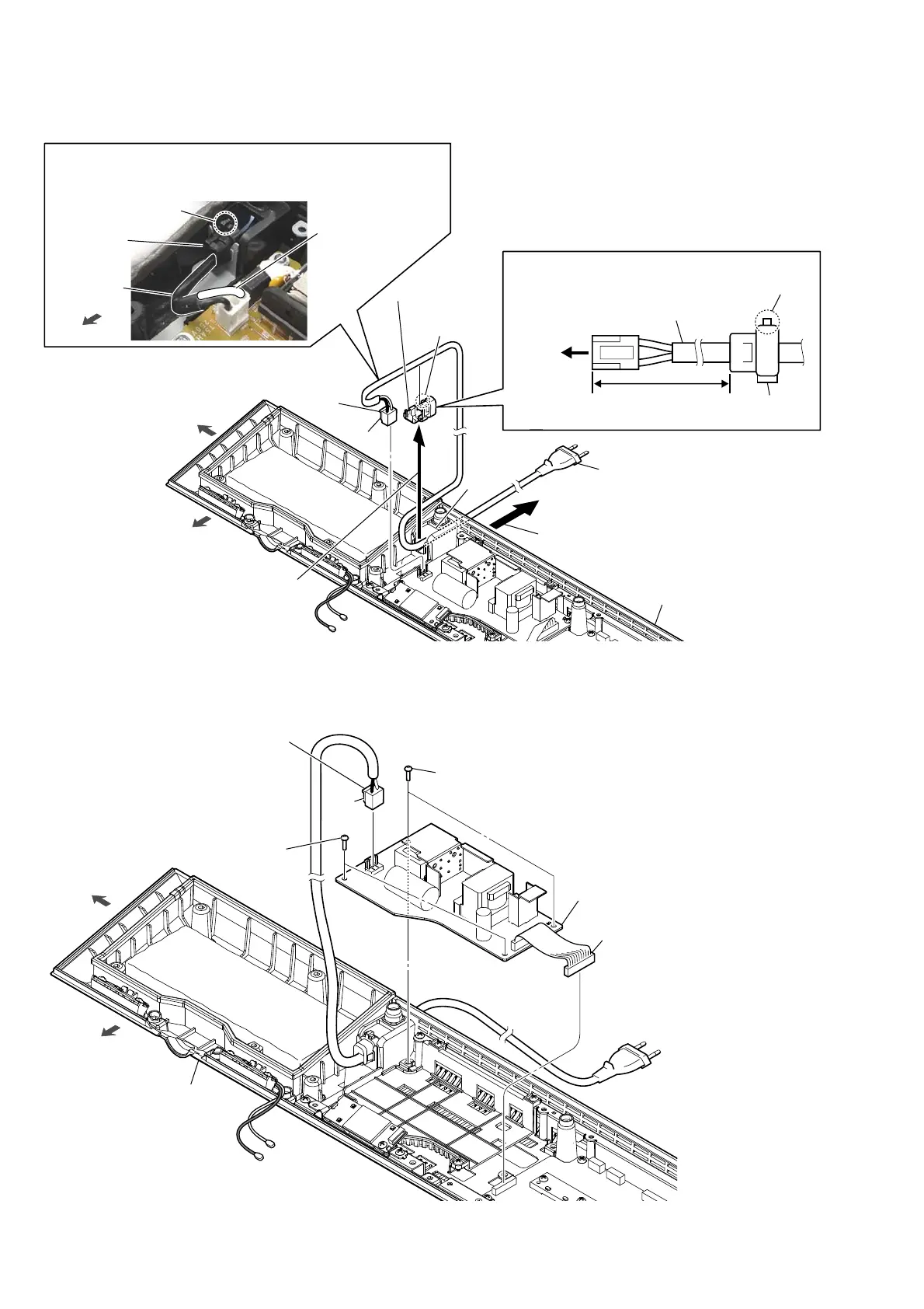
2-18. POWER CORD (AC1)
2-19. POWER BOARD
3RZHUFRUGEORFNVHWWLQJ
hole
2 Lift up the cord bushing (FBS001)
in the direction of the arrow.
3 Draw out the power cord
block from the hole.
6 power cord
(AC1)
5 cord bushing
(FBS001)
4 Unlock.
lock side
power cord
cord bushing
(FBS001)
front side
left side
claw
side
bottom cabinet block
Note:
When installing the power cord block, check the direction and position
of lock side of the cord bushing (FBS001) and install correctly.
front side
1 power cord
connector
(CN901)
[white] : US, CND
[blue] : Except US, CND
power cord
(AC1)
cord bushing
(FBS001)
lock side
120 +10, -0 mm
to
POWER
board
,QVWDOODWLRQSRVLWLRQRIWKHFRUGEXVKLQJ)%6
3 two screws
(BVTP3 u 8)
1 power cord connector
(CN901)
claw
side
front side
left side
bottom cabinet block
3 two screws
(BVTP3 u 8)
4 POWER board
2 connector (CN6001)
Note:
Before connect this connector,
make sure to refer to
“CAPACITOR ELECTRICAL
DISCHARGE PROCESSING”
on page 4.
Ver. 1.1