HT-NT5
21
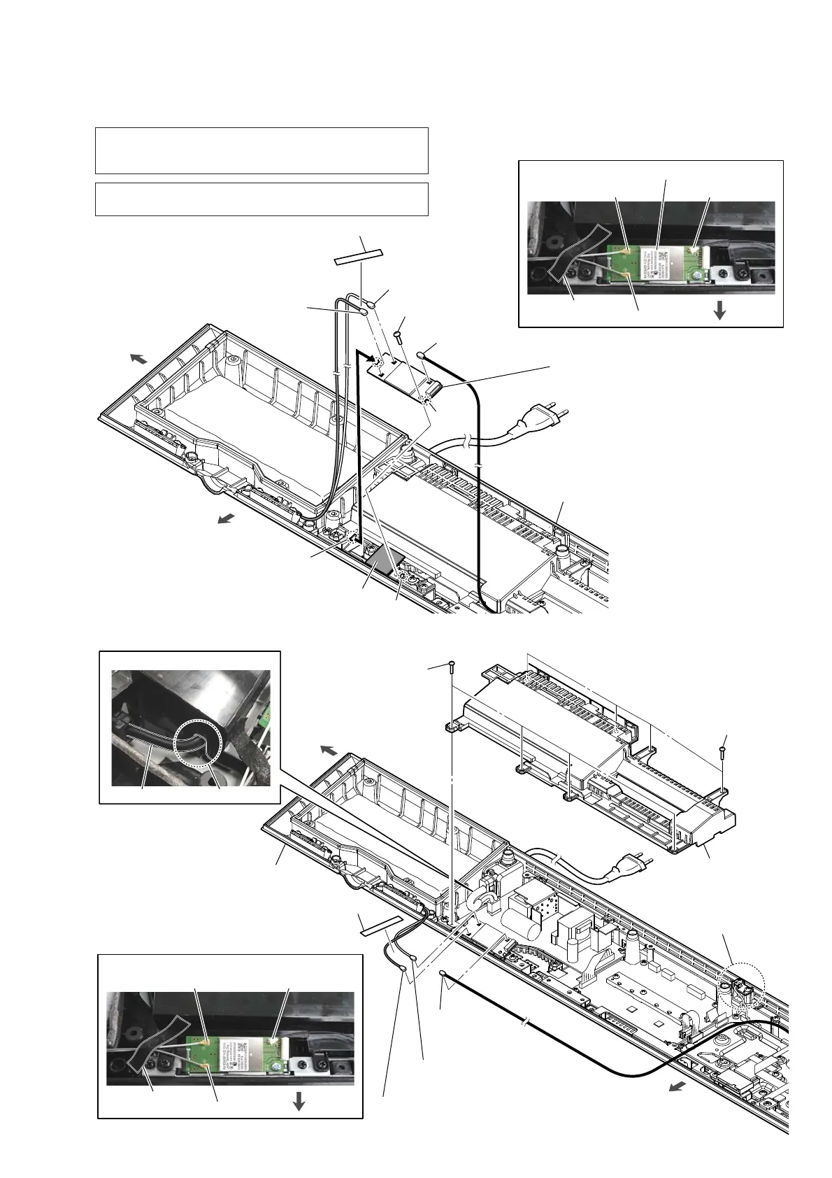
2-16. WLAN/BT COMBO CARD (WIFI1)-2
2-17. INSULATOR (TOP)
4 claw
rib
groove
5 WLAN/BT combo card (WIFI1)
Note 3:
When installing the WLAN/BT combo
card, align the rib and groove.
2 coaxial connector (No. 3)
[gray]
2 coaxial connector (No. 2)
[white]
2 coaxial connector (No. 1)
[black]
3 screw
(BVTP3 u 8)
1 saranet cushion
radiation sheet
See Note 2
saranet cushion
[white]: No. 2
[gray]: No. 3
[black]: No. 1
:LUHVHWWLQJ
front side
left side
bottom cabinet block
front side
WLAN/BT combo card (WIFI1)
saranet cushion
[white]: No. 2
[gray]: No. 3
[black]: No. 1
:LUHVHWWLQJ
front side
2 coaxial connector (No. 3)
[gray]
2 coaxial connector (No. 2)
[white]
2 coaxial
connector
(No. 1) [black]
1 saranet cushion
3RZHUFRUGVHWWLQJ
power cord
slot
3 four screws
(BVTP3 u 10)
3 four screws
(BVTP3 u 10)
4 insulator (top)
REPEATER board
Note:
Be careful not to damage
the REPEATER board.
front side
bottom cabinet block
left side
Note 1: When the WLAN/BT combo card (Ref. No. WIFI1) is re-
placed, refer to “NOTE OF REPLACING THE MB-1509
BOARD OR WLAN/BT COMBO CARD” on page 5.
Note 2: If the radiation sheet is damaged, be sure to replace them with
new parts.