SA-WCT180
6
SECTION 2
DISASSEMBLY
• This set can be disassembled in the order shown below.
2-1. DISASSEMBLY FLOW
Note: Follow the disassembly procedure in the numerical order given.
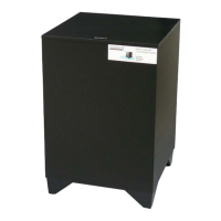
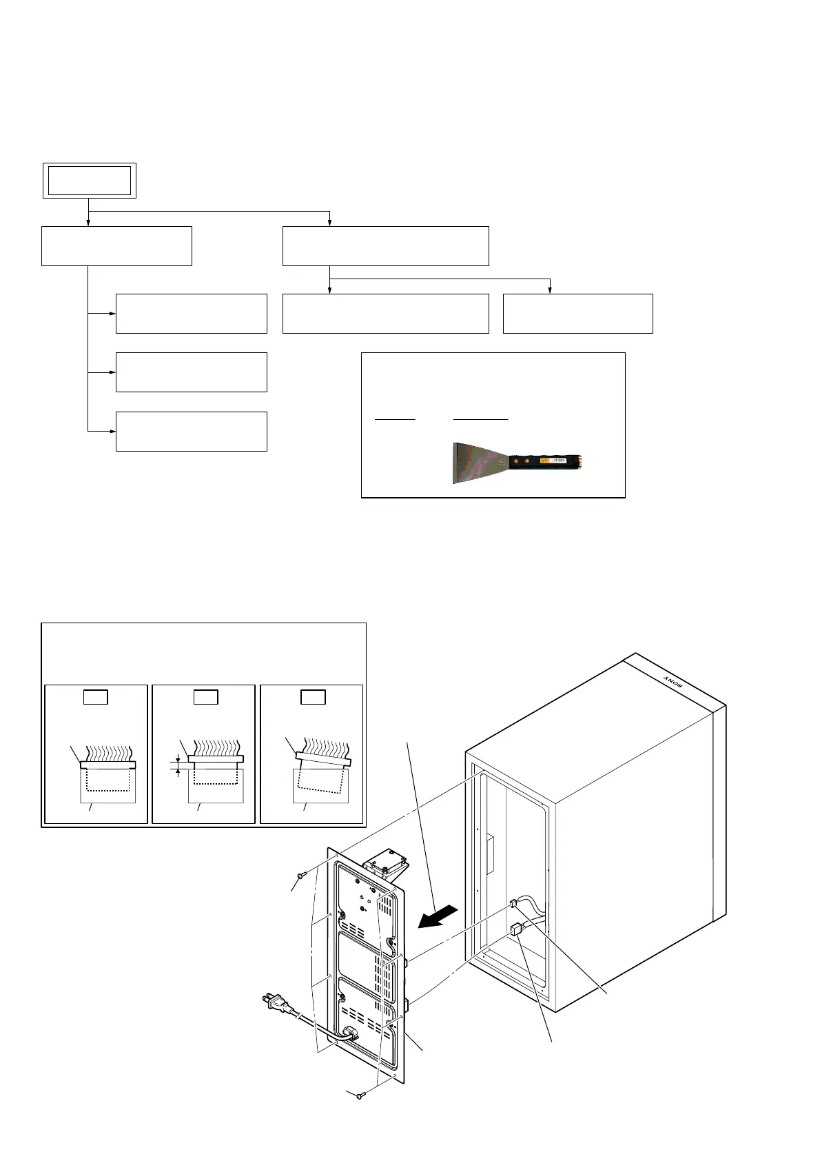
2-2. AMP BLOCK
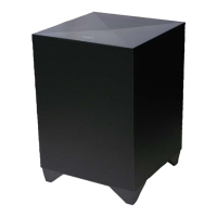
SET
2-2. AMP BLOCK
(Page 6)
2-3. MAIN BOARD
(Page 7)
2-4. POWER BOARD
(Page 8)
2-5. AC CORD (AC1)
(Page 9)
2-8. GRILLE (SW) ASSY
(Page 11)
2-7. LOUDSPEAKER (13 cm) (SP1)
(Page 11)
2-6. FRONT PANEL BLOCK
(Page 10)
JIG
When disassembling the unit, use the following
jig for speaker removal.
Part No. Description
J-2501-238-A JIG FOR SPEAKER REMOVAL
– Rear view –
1 four screws
(3.5 u 14 B)
2 Remove the AMP block
in the direction of the
arrow.
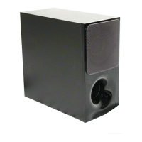
4 LED board cable
connector (XS5)
3 speaker cable connector
(XP8)
5 AMP block
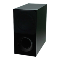
1 four screws
(3.5 u 14 B)
Insert only part way.Insert straight into
the interior.
connector
Insert at a slant.
connector
connector
connector
connector connector
OK NG NG
How to install the connector
Insert the connector straight into the interior.
There is a possibility that using this unit without
the connector correctly installed will damage it.
 Loading...