EasyManua.ls Logo

Sony SA-WCT770 User Manual

Sony SA-WCT770
38 pages
To Next Page IconTo Next Page
Page #1 background imageLoading...
Page #1 background image
SERVICE MANUAL
Sony Corporation
Published by Sony Techno Create Corporation
SA-WCT770
ACTIVE SUBWOOFER
9-893-983-02
2014F33-1
©
2014.06
US Model
Canadian Model
AEP Model
UK Model
Australian Model
Chinese Model
Saudi Arabia Model
Singapore Model
Taiwan Model
Ver. 1.1 2014.06
SA-WCT770 is the active subwoofer in HT-CT770.
All of the units included in the HT-CT770 (SA-WCT770/
SA-CT770) are required to con rming operation of SA-
WCT770. Check in advance that you have all of the units.
For the TEST MODE for this unit, refer to the service manual of HT-CT770.
SPECIFICATIONS
POWER OUTPUT (reference)
120 W (per channel at 4 ohms, 100 Hz) (Except Chinese model)
75W (per channel at 4 ohms, 100 Hz) (Chinese model)
Speaker system
Subwoofer system, Bass reflex
Speaker
160 mm (6 3/8 in) cone type
Rated impedance
4 ohms
Power requirements
120 V AC, 60 Hz (US and Canadian models)
220 V - 240 V AC, 50 Hz/60 Hz (AEP, UK, Australian, Chinese and Singapore models)
110 V - 240 V AC, 50 Hz/60 Hz (Saudi Arabia model)
120 V AC, 50 Hz/60 Hz (Taiwan model)
Power consumption
On: 30 W
Standby mode: 0.5 W or less
Dimensions (approx.) (w/h/d)
271 mm × 404 mm × 271 mm
(10 3/4 in × 16 in × 10 3/4 in)
Mass (approx.)
8.8 kg (17 Ib 10 1/2 oz)
Speaker system
Wireless Sound Specification version 2.0
Frequency band
2.4 GHz (2.4000 GHz - 2.4835 GHz)
Modulation method
Pi / 4 DQPSK
Wireless receiver section
Design and specifications are subject to change without notice.

Other manuals for Sony SA-WCT770

Question and Answer IconNeed help?

Do you have a question about the Sony SA-WCT770 and is the answer not in the manual?

Sony SA-WCT770 Specifications

General IconGeneral
BrandSony
ModelSA-WCT770
CategorySubwoofer
LanguageEnglish

Summary

SERVICING NOTES

SAFETY CHECK-OUT

Procedures for ensuring safety after service, including AC leakage tests.

LEAKAGE TEST

Methods for measuring AC leakage current from exposed metal parts.

NOTES ON CHIP COMPONENT REPLACEMENT

Precautions for replacing chip components, especially tantalum capacitors.

UNLEADED SOLDER

Information on using and handling unleaded solder and its characteristics.

CAPACITOR ELECTRICAL DISCHARGE PROCESSING

Procedure to safely discharge capacitors before testing or replacement.

NOTE OF REPLACING THE IC104 ON THE SUB MAIN BOARD AND THE COMPLETE SUB MAIN BOARD

Guidance on applying compound when replacing IC104 or the entire SUB MAIN board.

MODEL IDENTIFICATION

Model Number Label

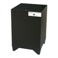
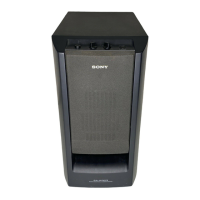
Identifying the unit by the model number label on the rear plate.

Destination Code Mapping

Table mapping destination codes to part numbers and regions.

DISASSEMBLY

DISASSEMBLY FLOW

A step-by-step guide for disassembling the unit in a sequential order.

REAR PANEL BLOCK

Procedure for removing the rear panel block of the subwoofer.

TOP PANEL BLOCK

Steps for safely removing the top panel block of the subwoofer.

SUB AMP BLOCK

Instructions for accessing and removing the subwoofer amplifier block.

POWER BOARD

Guide for disassembling and removing the power board.

SUB MAIN BOARD

Detailed steps for removing the main control board of the subwoofer.

LOUDSPEAKER

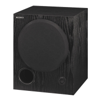
Method for removing and replacing the main loudspeaker unit.

TROUBLESHOOTING

ON/STANDBY lamp LED flashes in red (PROTECT)

Diagnosing and resolving issues when the PROTECT indicator flashes red.

ON/STANDBY lamp LED does not light up (Power is not turned on)

Troubleshooting steps when the unit fails to power on.

DIAGRAMS

BLOCK DIAGRAM

Overall system block diagram illustrating signal flow and major components.

SUB MAIN Board Diagrams

Printed wiring boards and schematic diagrams for the SUB MAIN board.

POWER Board Diagrams

Printed wiring board and schematic diagram for the POWER board.

IC Block Diagrams

Block diagrams illustrating the internal structure of key integrated circuits.

IC Pin Function Description

Detailed description of pin functions for major ICs on the SUB MAIN board.

EXPLODED VIEWS

OVERALL SECTION

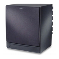
Exploded view of the entire subwoofer unit showing major assemblies.

SUB AMP SECTION

Exploded view of the subwoofer amplifier section, detailing its components.

SUBWOOFER CABINET SECTION

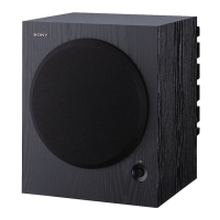
Exploded view of the subwoofer cabinet and speaker assembly.

ELECTRICAL PARTS LIST

CAPACITORS

List of all capacitor parts with their specifications and part numbers.

DIODES

List of all diode parts with their specifications and part numbers.

RESISTORS

List of all resistor parts with their specifications and part numbers.

TRANSISTORS

List of all transistor parts with their specifications and part numbers.

REVISION HISTORY

Version History

Record of revisions made to the service manual over time.

Related product manuals