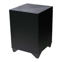
SA-WCT770
6
SECTION 2
DISASSEMBLY
• This set can be disassembled in the order shown below.
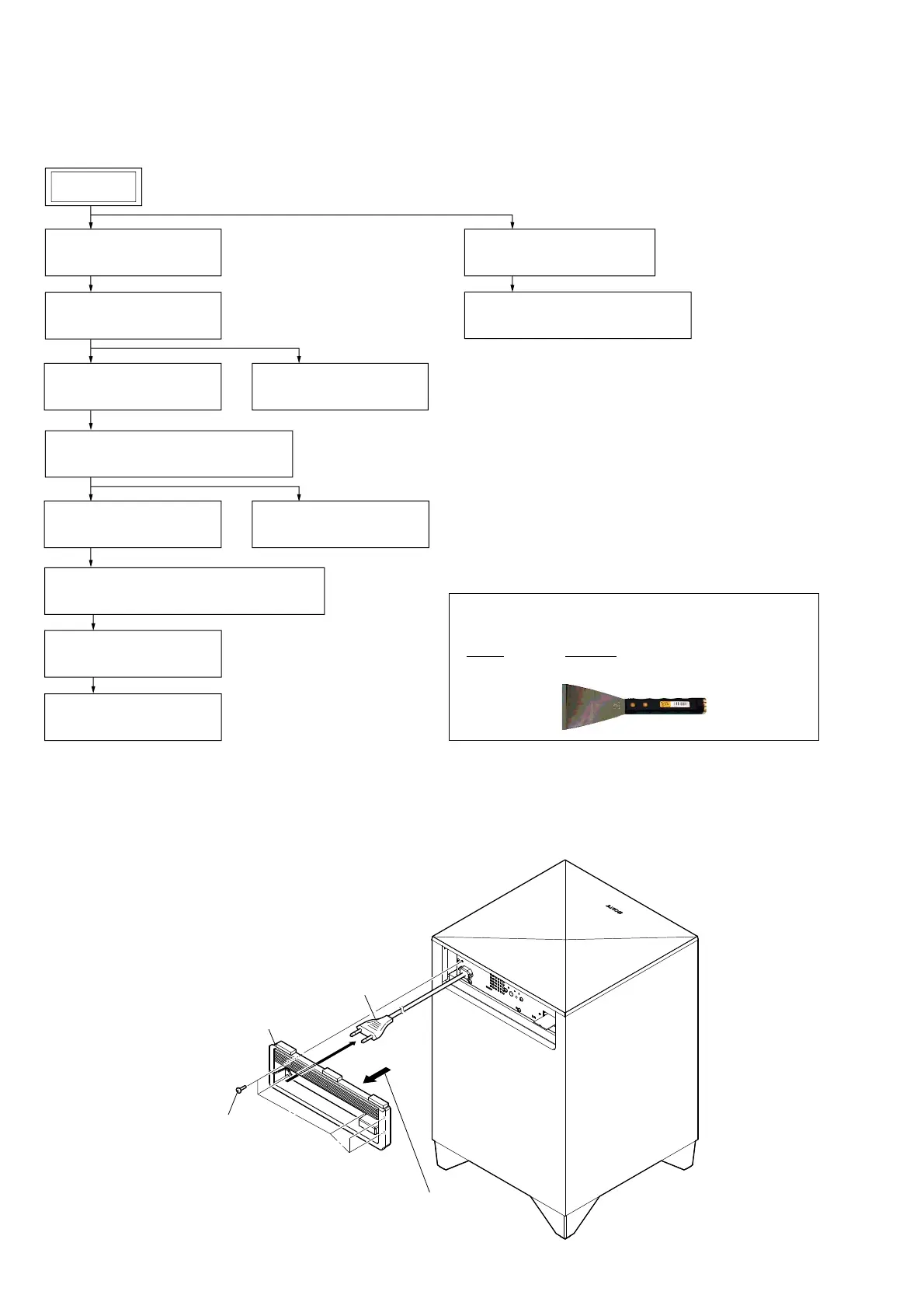
2-1. DISASSEMBLY FLOW
Note: Follow the disassembly procedure in the numerical order given.
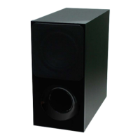
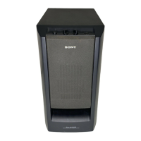
2-2. REAR PANEL BLOCK
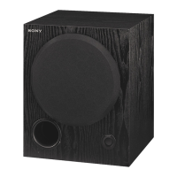
SET
2-8. POWER CORD (AC1)
(Page 10)
2-5. SUB AMP BLOCK
(Page 8)
2-2. REAR PANEL BLOCK
(Page 6)
2-3. TOP PANEL BLOCK
(Page 7)
2-7. POWER BOARD
(Page 9)
2-10. REAR PLATE BLOCK
(Page 11)
2-11. SUB MAIN BOARD
(Page 12)
2-9. RF MODULATOR (SWA12-4V RX) (RF1)
(Page 11)
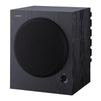
2-13. LOUDSPEAKER (16 cm) (SP1)
(Page 14)
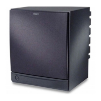
2-12. BOTTOM PANEL BLOCK
(Page 13)
2-4. SUB LED BOARD
(Page 8)
2-6. TOP PLATE BLOCK, FUSE (F900)
(Page 9)
1 five screws
(BVTP3 u 8)
3 Pull out the power cord.
2 Remove the rear panel block
in the direction of an arrow.
4 rear panel block
– Rear view –
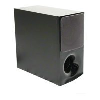
• JIG
When disassembling the set, use the following jig (for speaker
removal).
Part No. Description
J-2501-238-A JIG FOR SPEAKER REMOVAL