Do you have a question about the Sony SA-WP16 and is the answer not in the manual?
Guidelines for replacing chip components, including capacitor handling.
Information regarding the use and characteristics of unleaded solder.
Critical component warnings for safe operation and replacement.
Diagram illustrating the physical placement of circuit boards within the unit.
Detailed layout of the printed circuit board for the main operational section.
Circuit schematic for the main operational section of the device.
Functional block diagram illustrating the operation of the main IC.
Exploded view of the front part of the unit, showing speaker and mounting hardware.
Exploded view of the rear part of the unit, detailing major assemblies and components.
List of electrical components for the input control section.
List of electrical components for the LED indicator board.
List of resistors and diodes for the main board.
List of integrated circuits and transistors for the main board.
List of components for the switch board.
List of components for the trans board.
List of miscellaneous parts including cords, fuses, and speakers.
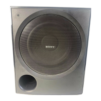
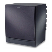
| Type | Active Subwoofer |
|---|---|
| Manufacturer | Sony |
| Model | SA-WP16 |
| Bass Reflex | Yes |
| Frequency Response | 28Hz - 200Hz |
| Inputs | RCA |