EasyManua.ls Logo

Sony SA-WP785 User Manual

Sony SA-WP785
14 pages
To Next Page IconTo Next Page
Page #1 background imageLoading...
Page #1 background image
SERVICE MANUAL
Sony Corporation
Home Audio Division
Published by Sony Techno Create Corporation
E Model
Australian Model
ACTIVE SUBWOOFER
9-887-652-01
2007D16-1
© 2007.04
Ver. 1.0 2007.04
SPECIFICATIONS
SA-WP785
SA-WP785 is the sub woofer section
in HT-DDW785.
•Abbreviation
AUS : Australian model
SP : Singapore model
Speaker system Active subwoofer,
magnetically shielded
Speaker unit 200 mm cone type
Enclosure type Acoustically loaded bass
reflex
RMS output 190 W
Power requirements
Power consumption 80 W
Dimensions (w/h/d) (Approx.)
270 × 330 × 373 mm
including front panel
Mass (Approx.) 8.3 kg
Area code Power requirements
AUS 240 V AC, 50Hz
SP 230 – 240 V AC, 50/60 Hz
Input
LINE IN (input pin jacks)
Design and specifications are subject to
change without notice.
Question and Answer IconNeed help?

Do you have a question about the Sony SA-WP785 and is the answer not in the manual?

Sony SA-WP785 Specifications

General IconGeneral
BrandSony
ModelSA-WP785
CategorySubwoofer
LanguageEnglish

Summary

Specifications

Speaker System

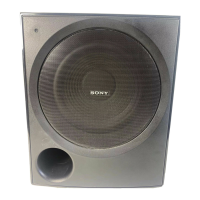
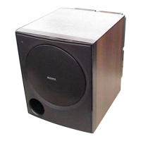
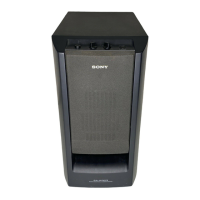
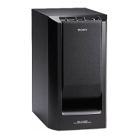
Active subwoofer, magnetically shielded.

Speaker Unit

200 mm cone type.

Enclosure Type

Acoustically loaded bass reflex.

Input

LINE IN (input pin jacks).

Power Requirements

Specifies voltage and frequency for AUS and SP regions.

Dimensions

270 x 330 x 373 mm including front panel.

Mass

8.3 kg.

Unleaded Solder

Lead Free Mark (LF)

Identifies solder containing no lead.

Unleaded Solder Properties

Higher melting point, strong viscosity, usable with ordinary solder.

Safety Related Component Warning

Critical Component Identification

Marks critical components for safe replacement with specified Sony parts.

Section 1 Diagrams

Printed Wiring Board Notes

Explains symbols for printed wiring board diagrams.

Schematic Diagram Notes

Explains symbols for schematic diagrams.

Circuit Board Locations

Shows physical placement of circuit boards.

IC Block Diagrams

NJM4565D ICs (IC202, IC203)

Block diagram for dual operational amplifiers.

uPC1237C-A IC (IC500)

Block diagram for protection control IC.

Block Diagram

Overall Block Diagram

Illustrates main functional blocks and signal flow.

Printed Wiring Boards - Main Section

Main Board PWB Diagram

Printed wiring board layout for the main section.

Schematic Diagram - Main Section

Main Section Schematic

Detailed schematic of main audio processing and control circuits.

Printed Wiring Boards - Power Section

Power Section PWB Diagrams

PWB layouts for Power Trans and Switch boards.

Schematic Diagram - Power Section

Power Section Schematic

Schematic diagram of power supply and switching circuits.

Exploded Views

Overall Section Exploded View

Visual breakdown of unit components for assembly.

Electrical Parts List

Input Control Board Components

List of electronic components for the input control board.

LED Board Components

List of electronic components for the LED board.

Main Board Components

List of electronic components for the main board.

Power Trans Board Components

List of components for the power transformer board.

Switch Board Components

List of components for the switch board.

Miscellaneous Components

List of general components like power cords, fuses, and speakers.

Revision History

Initial Revision 1.0

Records the initial release version and date of the service manual.

Related product manuals