Do you have a question about the Sony SA-WP890 and is the answer not in the manual?
Technical specifications for the subwoofer, including power output and requirements.
Essential safety procedures and leakage tests for serviced units.
Guidance on the characteristics and use of unleaded solder.
High-level overview of the subwoofer's signal flow and functional blocks.
Visual layout of components and traces on the main circuit board.
Detailed electrical circuit diagram for the main section.
Visual layout of components and traces on the power supply board.
Detailed electrical circuit diagram for the power supply section.
Exploded view illustrating the physical assembly and part identification.
List of components for the input control, LED, and main circuit boards.
List of components for the power transformer and switch circuit boards.
| Type | Active Subwoofer |
|---|---|
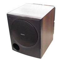
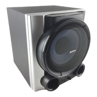
| Model | SA-WP890 |
| Brand | Sony |
| Power Output | 100W |
| Dimensions (W x H x D) | 280 x 345 x 420 mm |
| Weight | 11 kg |
| Amplifier Power | 100W |
| Frequency Response | 20Hz - 200Hz |
| Inputs | Line In |