Do you have a question about the Sony SA-WMSP1 and is the answer not in the manual?
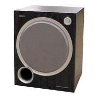
Details on the audio system, speaker unit, amplifier, and frequency range.
Covers power requirements, consumption, dimensions, and mass.
Procedure and methods for checking AC leakage current on exposed metal parts.
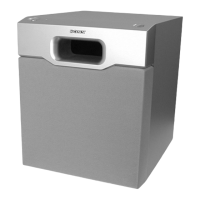
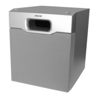
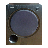
Identifies the power button, power indicator, and level dial on the top view.
Diagram showing the placement of the main, control, LED, power IC, and switch boards.
Layouts of the printed wiring for the main, control, LED, power IC, and switch boards.
Detailed circuit schematics for the main, control, power IC, LED, and switch boards.
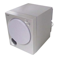
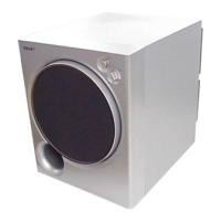
Diagram illustrating the assembly of the front panel, grille, and speaker unit.
Diagram showing the exploded components of the amplifier section, including boards and power transformer.
List of electrical components for the control board, including capacitors, connectors, and ICs.
List of electrical components for the LED board, including connectors and diodes.
List of electrical components for the main board, including capacitors, connectors, diodes, and fuses.
List of electrical components for the power IC board, including capacitors, connectors, ICs, and resistors.
List of electrical components for the switch board, including connectors and switches.
| Type | Active Subwoofer |
|---|---|
| Amplifier Power | 100 Watts |
| Frequency Response | 28 Hz - 200 Hz |
| Connectivity | Wired |
| Inputs | Line Level |
| Phase Switch | Yes |
| Weight | 22.05 lbs |
| Driver Size | 8 inches |
| Crossover Frequency | 50Hz - 200Hz (variable) |
| Dimensions (W x H x D) | 200 x 290 x 290 mm |