EasyManua.ls Logo

Sony SA-WMS556 User Manual

Sony SA-WMS556
16 pages
To Next Page IconTo Next Page
Page #1 background imageLoading...
Page #1 background image
SERVICE MANUAL
Sony Corporation
Home Audio Company
Published by Sony Engineering Corporation
AEP Model
UK Model
SUBWOOFER
9-877-843-01
2004E0478-1
© 2004.05
Ver 1.0 2004.05
SPECIFICATIONS
SA-WMS356/WMS556
SA-WMS356/WMS556 are the subwoofer
section in SA-VE356T/VE556H.
Speaker system Active subwoofer,
magnetically shielded
Speaker unit Woofer: 15 cm × 2, cone type
Enclosure type Acoustically loaded
Bass Reflex
Reproduction frequency range
28 Hz - 200 Hz
Amplifier section
Continuous RMS power output
SA-WMS356:
120 W (6 ohms, 100 Hz,
10 % THD)
SA-WMS556:
150 W (6 ohms, 100 Hz,
10 % THD)
Inputs
INPUT (input pin jack)
General
Power requirements
230 - 240 V AC, 50/60 Hz
Power consumptions
120 W
1 W (standby mode)
Dimensions (w/h/d)
Approx. 180 × 405 × 501 mm,
including front grille
Mass Approx. 12 kg
Design and specifications are subject to change
without notice.
Question and Answer IconNeed help?

Do you have a question about the Sony SA-WMS556 and is the answer not in the manual?

Sony SA-WMS556 Specifications

General IconGeneral
BrandSony
ModelSA-WMS556
CategorySubwoofer
LanguageEnglish

Summary

SERVICE MANUAL

SPECIFICATIONS

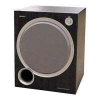
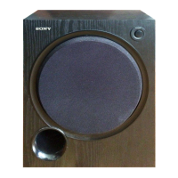
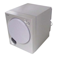
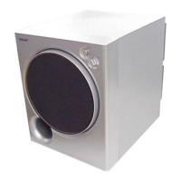
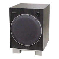
Technical specifications for the SA-WMS356/WMS556 subwoofer.

UNLEADED SOLDER

LEAD FREE MARK CHARACTERISTICS

Properties and handling guidelines for unleaded solder and its mark.

SAFETY WARNINGS

SAFETY-RELATED COMPONENTS IDENTIFICATION

Identification of critical safety components and replacement guidance.

DIAGRAMS AND NOTES

SCHEMATIC & WIRING BOARD INTERPRETATION

Notes for interpreting schematic symbols, measurements, and wiring boards.

CIRCUIT BOARD LOCATIONS

Diagram illustrating the physical placement of the unit's circuit boards.

IC BLOCK DIAGRAM

POWER AMP IC BLOCK DIAGRAM

Block diagram illustrating the IC701 STK404-140S on the power amp board.

PRINTED WIRING BOARD - MAIN SECTION

MAIN BOARD SEMICONDUCTOR LIST

List of semiconductors and their reference locations on the main board.

SCHEMATIC DIAGRAM - MAIN SECTION

MAIN BOARD SCHEMATIC DETAILS

Schematic detailing components and connections on the main board.

POWER AMP BOARD SCHEMATIC DETAILS

Schematic detailing components and connections on the power amp board.

PRINTED WIRING BOARD - CONTROL SECTION

CONTROL BOARD SEMICONDUCTOR LIST

List of semiconductors and their reference locations on the control board.

SCHEMATIC DIAGRAM - CONTROL SECTION

CONTROL BOARD SCHEMATIC DETAILS

Schematic detailing components and signal paths on the control board.

EXPLODED VIEWS

FRONT PANEL ASSEMBLY VIEW

Exploded view and parts list for the front panel assembly.

REAR COVER SECTION

REAR COVER ASSEMBLY VIEW

Exploded view and parts list for the rear cover and associated components.

BOTTOM PANEL SECTION

BOTTOM PANEL ASSEMBLY VIEW

Exploded view and parts list for the bottom panel and speaker mounting.

ELECTRICAL PARTS LIST

CONTROL BOARD COMPONENTS

List of electrical components for the control board.

LED BOARD COMPONENTS

List of electrical components for the LED board.

ELECTRICAL PARTS LIST

MAIN BOARD COMPONENTS

List of electrical components for the main board.

POWER AMP BOARD COMPONENTS

List of electrical components for the power amp board.

ELECTRICAL PARTS LIST

POWER SUPPLY BOARD COMPONENTS

List of electrical components for the power supply board.

POWER SWITCH BOARD COMPONENTS

List of electrical components for the power switch board.

REVISION HISTORY

REVISION HISTORY DETAILS

Record of manual revisions, including version, date, and description.

Related product manuals