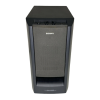
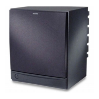
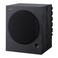
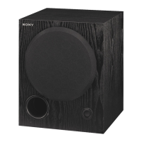
SA-WCT770
28
• IC Pin Function Description
SUB MAIN BOARD IC100 R5F212BASNFP (SYSTEM CONTROLLER)
Pin No. Pin Name I/O Description
1 NO USE O Not used
2 S-AIR_DATA I/O Two-way S-AIR data with the RF modulator
3 FW_MODE I Not used
4, 5 NO USE O Not used
6 RESET I
System reset signal input terminal “L”: reset
For several hundreds msec. after the power supply rises, “L” is input, then it change to “H”
7 Xout O System clock output terminal (20 MHz)
8 Vss - Ground terminal
9 Xin I System clock input terminal (20 MHz)
10 Vcc1 - Power supply terminal (+3.3V)
11 NO USE O Not used
12 P_CONT2 O Power on/off control signal output terminal “H”: power on
13 P_CONT1 (3.3V) O Power on/off control signal output terminal “H”: power on
14 P_CONT_PVDD O Power on/off control signal output terminal “H”: power on
15 to 20 NO USE O Not used
21 LED_GREEN O LED drive signal output terminal for the on/standby lamp (green color) “H”: LED on
22 LED_RED O LED drive signal output terminal for the on/standby lamp (red color) “H”: LED on
23 PAIRING_LED O LED drive signal output terminal Not used
24 NO USE O Not used
25 DAMP_SHIFT O Serial data transfer clock signal output to the stream processor
26 NO USE O Not used
27 DAMP_SCDT O Serial data output to the stream processor
28 DRIVE_RST (EN) O Reset signal output to the digital power amplifi er “L”: reset
29 DAMP_INIT O Reset signal output to the stream processor “L”: reset
30 DAMP_OVF I Overfl ow detection signal input from the stream processor “L”: overfl ow is detected
31 DAMP_LATCH O Serial data latch pulse signal output to the stream processor
32 DAMP_SOFT_MUTE O Soft muting on/off control signal output to the stream processor “L”: muting on
33 DAMP_OVF2 I Overfl ow detection signal input terminal Not used
34 DAMP_LATCH2 O Serial data latch pulse signal output terminal Not used
35 NO USE O Not used
36 AC_CUT I AC cut detection signal input terminal “L”: AC cut is detected
37 FW_TxD O Transmit data output terminal for fl ash writing
38 FW_RxD I Receive data input terminal for fl ash writing
39 to 41 NO USE O Not used
42 PVDD_SD_EN O Shutdown signal output terminal “L”: shutdown
43 DC_DET I Speaker DC detection signal input terminal “L”: speaker DC is detected
44 NO USE O Not used
45 DRIVE_SD I Shutdown signal input from the stream processor “L”: shutdown
46 S-AIR FREQ DET I S-AIR module frequency detection signal input terminal Not used
47 S-AIR DET I S-AIR detection signal input terminal Not used
48 S-AIR_GPIO2 I S-AIR interrupt signal input from the RF modulator
49 KEY_POWER I Power key input terminal
50 S-AIR_RESET O S-AIR reset signal output to the RF modulator “L”: reset
51 KEY_PAIRING I LINK key input terminal
52 SUR_MODE_SW O Not used
53 SHIMUKE O Destination setting terminal Not used
54 MODEL O Model setting terminal Not used
55 FAN_ON O Fan motor drive signal output terminal Not used
56 FAN_DET I Fan motor detection signal input terminal Not used
57 S-AIR_RF_FB O Not used
58 NO USE O Not used
59 Vss - Ground terminal
60 NO USE O Not used
61 Vref I Reference voltage (+3.3V) input terminal
62 Vcc1 - Power supply terminal (+3.3V)
63 NO USE O Not used
64 S-AIR_CLK O S-AIR clock signal output to the RF modulator
 Loading...