— 144 —
SCPH-30002D/30003D/30004D
SECTION 4
PRINTED WIRING BOARDS AND SCHEMATIC DIAGRAMS
for SCPH-30002D/30003D/30004D
THIS NOTE IS COMMON FOR PRINTED WIRING
BOARDS AND SCHEMATIC DIAGRAMS.
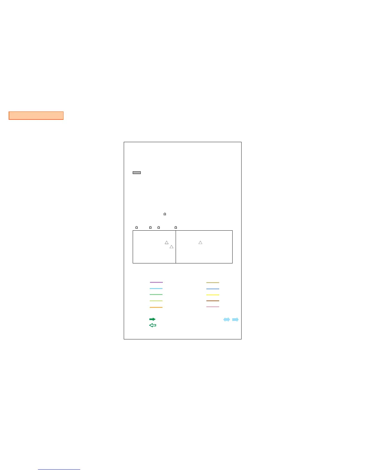
Note on Printed Wiring Boards :
•
•
Through hole is omitted.
: Pattern on the side which is seen.
Note on Schematic Diagram :
•
•
•
•
Use caution when replacing chip parts.
New parts must be attached after removal of chip.
Be careful not to heat the minus side of tantalum capacitor,
because it is damaged by the heat.
All capacitors are in µF unless otherwise noted. pF : µµF 50 WV
or less are not indicated except for electrolytics and tantalums.
All resistors are in and 1/4 W (Chip resisters : 1/10W) unless
otherwise specified.
Chip resistors are 1/8 W or 1/10 W unless otherwise noted.
k : 1000 , M : 1000 k .
Note :
The components
identified by mark
!
or
dotted line with mark
!
are critical for safety.
Replace only with part
number specified.
Note :
Les composants identifies par
une marque
!
sont critiques
pour la securite.
Ne les remplacer que par une
piece portant le nubero specifie.
Unit of voltage is V (volt)
•
•
•
•
•
•
•
+12V :
+8.0V :
+5.0V :
+3.5V :
+3.4V :
IN :
OUT :
•
•
•
•
•
•
+3.3V :
+2.5V :
+1.8V :
+1.7V :
+1.5V :
Main Signal Line : ,
Note on DC Power line :
Reproduction Prohibited
 Loading...