EasyManua.ls Logo

Sony SDM-M61 User Manual

Sony SDM-M61
45 pages
To Next Page IconTo Next Page
Page #1 background imageLoading...
Page #1 background image
SDM-M61
SERVICE MANUAL
US Model
Canadian Model
AEP Model
SPECIFICATIONS
LCD panel
Input signal format
Resolution
Video input connector
Input signal levels
Audio output
Headphones jack
Audio in jack
Panel type: a-Si TFT Active Matrix
Picture size: 16.0 inch
RGB operating frequency*
Horizontal: 28-92 kHz
Vertical: 48-85 Hz
Horizontal: Max. 1280 dots
Vertical: Max. 1024 lines
Analog RGB: HD15
Digital/Analog RGB: DVI-I 29 pins
Analog RGB video signal:
0.7 Vp-p, 75Ω, positive
SYNC signal:
TTL level, 2.2kΩ,
Positive or negative
(Separate horizontal and vertical,
or composite sync)
0.3 Vp-p, 75Ω, negative
(Sync on green)
Digital RGB video signal:
TMDS (single link)
1W x 2
Stereo minijack
Accepts impedance of 16-48 Ω
Stereo minijack x 2
Accepts impedance of 47 kΩ
Accepts level 0.5 Vrms
Power requirements 100-240 V, 50-60 Hz,
0.7 - 0.35A
Power consumption Max. 35W
Operating temperature 5-35
Dimensions (width/height/depth)
Display (upright):
Approx. 400 x 357 x 180 mm
(15¾ x 14 x 7 inches)
(with stand)
Approx. 400 x 318 x 57 mm
(15¾ x 12 x 2¼ inches)
(without stand)
Mass Approx. 5.4 kg (11 1b 14 oz) (with
stand)
Plug & Play
DDC2B
* Recommended horizontal and vertical timing condition
• Horizontal sync width duty should be more than 4.8% of total
horizontal time or 0.8 μs, whichever is larger.
• Horizontal blanking width should be more than 2.5 μsec.
• Vertical blanking width should be more than 450μsec.
Design and specifications are subject to change without notice.
TFT LCD COLOR COMPUTER DISPLAY
Question and Answer IconNeed help?

Do you have a question about the Sony SDM-M61 and is the answer not in the manual?

Sony SDM-M61 Specifications

General IconGeneral
Screen Size15 inches
Display TypeLCD
Resolution1024 x 768
Aspect Ratio4:3
Brightness250 cd/m²
Response Time25 ms
ConnectivityVGA
Input ConnectorsVGA
Power Consumption30 W

Summary

Power saving function

Automatic picture quality adjustment function

SAFETY CHECK-OUT

LEAKAGE TEST

Details on testing AC leakage from exposed metal parts to earth ground.

DISASSEMBLY

Bezel Assy. and Back Cabinet Removal

Procedure for removing the front bezel and rear cabinet.

TFT Panel and Chassis Removal

Steps for detaching the TFT panel and main chassis.

Inverter Board Removal

Guide for removing the inverter board.

A Board Removal

Instructions for removing the main control board (A Board).

ADJUSTMENTS

Functional Alignment (1)

Procedures for entering service mode and performing initial alignment.

Functional Alignment (2)

Details on color and geometry adjustments using alignment software.

Table 1 & 2

Provides default data and specifications for analog color adjustment.

Timing Specification

Lists detailed timing parameters for various preset video modes.

SCHEMATIC DIAGRAMS

Block Diagrams

High-level block diagram illustrating the main functional units.

Schematic Diagram of A (a-e) Board

Detailed circuit diagrams for the main A Board (multiple sheets).

Schematic Diagram of H Board

Circuit diagram for the H Board, likely related to controls.

Schematic Diagram of J Board

Circuit diagram for the J Board, likely related to audio output.

EXPLODED VIEWS

LCD Monitor

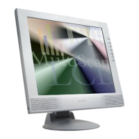
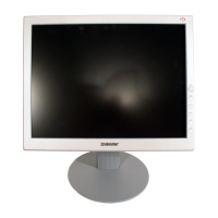
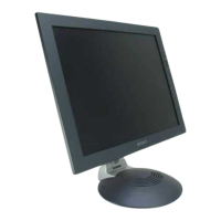
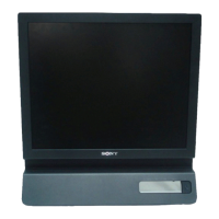
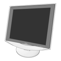
Illustrated breakdown of the LCD monitor assembly with part references.

Packing Materials

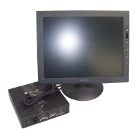
Lists all components included in the product packaging.

ELECTRICAL PARTS LIST

Related product manuals