EasyManua.ls Logo

Sony SL-2710 - Table of Contents

Sony SL-2710
144 pages
Print Icon
To Next Page IconTo Next Page
To Previous Page IconTo Previous Page
Loading...
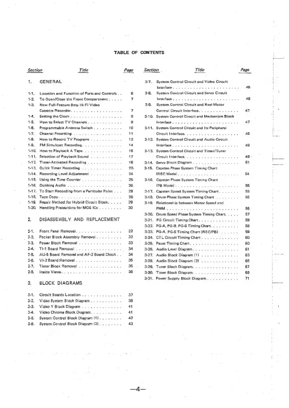
TABLE
OF
CONTENTS
Section
Title
1.
GENERAL
1-1,
Location
and
Function
of
Parts
and
Contrats
.
.
1-2,
To
Open/Ciose
the
Front
Compartment...
.
.
1-3.
New
Full-Feature
Beta
Hi-Fi
Video
Cassette
Recorder.
1-4,
Setting
the
Ciock
.
1-5.
How
to
Select
TV
Channels
.
1-6,
Programmable
Antenna
Switch
.
4-7,
Channel
Presetting
4-8.
How
to
Record
TV
Programs
1-9.
FM
Simulcast
Recording.
. .
1-10.
How
to
Playback
A
Tape.
. .
ens
1-11,
Selection
of
Playback
Sound
......
4-12,
Timer-Activeted
Recording
.......
1-13,
Quick
Timer
Recording
........,
4-14,
Recording
Level
Adjustment
1-15,
Using
the
Time
Counter
.
.
wee
ae
1-16.
Dubbing
Audio...
1
ee
ee
ee
ee
1-17.
To
Start
Recording
from
a
Particular
Point
. .
.
1-18,
Tape
Copy
4-19,
Repair
Method,
for
Hybrid
Circuit
Block
.
1-20.
Handling
Precautions
for
MOS
ICs.
. .
2.
DISASSEMBLY
AND
REPLACEMENT
2-4.
Front
Panel
Removal...
....-5.5-
wee
2-2,
Pocket
Block
Assembly
Removal.
.
. .
2-3,
Power
Block
Removal...
.
2-4,
TI-1
Board
Removal
be
2-5,
AU-6
Board
Removal
and
AF-2
Board
Check
.
246,
VI-2
Board
Removal
.
2.7,
Timer
Block
Removal...
.
:
2-8.
Inside
Views.
.......-
bee
eee
eee
3,
BLOCK
DIAGRAMS
3+,
Circuit
Boards
Location...
62...
eee
3-2.
Video
System
Block
Diagram
3-3.
Video
Y
Block
Diagram
.
3-4,
Video
Chroma
Block.
Diagram...
.
. .
3-5.
System
Contro!
Block
Diagram
{1).......
+
3-6.
System
Control
Block
Diagram
(2}......-.
Page
37
a
4
42
43
Section
Title
Page
3-7.
System
Control
Circuit
and
Video
Circuit
Inndbrtsce
wre
Sted
aatevite
sdsshied«
caseetayaes
45
3-8.
System
Control
Circuit
and
Servo
Circuit
Writertiom
sss
ie-ysdic,
costar
yeckas
At hg
eanrery
46
3-9,
System
Control
Circuit
and
Ree!
Motor
Control
Circuit
Interface.
47
3-10.
System
Control
Circuit
and
Mechanism
Block
LRSEEDOM
a:
ie
oles
Groth
ne
oapa,a
ype
o
ees
47
3-11,
System
Control
Circuit
and
Its
Peripheral
Circuit
Interface...
2...
oe
‘
tee
48
3-12,
System
Control
Circuit
and
Audio
Circuit
Interface...
49
3-13.
System
Control
Circuit
and
Timer/Tuner
Circuit
Interface,
ee
49
3-44.
Servo
Block
Diagram.
51
3-15.
Capstan
Phase
System
Timing
Chart
(REC
Mode)...
.....
Tanda
ted
Eats
54
3-16.
Capstan
Phase
System
Timing
Chart
(PB
Mode}.
cece
cece
cece
e
eens
BS
3-17,
Capstan
Speed
System
Timing
Chart.
55
3-18.
Drum
Phase
System
Timing
Chart
.
.
56
3-19.
Reiationship
between
Motor
Speed
and
PWM...
ee
eee
Boon
see
56
3-20.
Drum
Speed
Phase
System
Timing
Chart,....
87
3-21,
FG
Circuit
Timing
Chart...
6.4.60.
-6
5
58
3-22.
PG-A,
PG-B,
PG-S
Timing
Chart.
. :
59
3-23.
PG-A,
PG-S
Timing
Chart
(REC/PB)
59
3-24.
CTL
Circuit
Timing
Chart...
. .
B
60
3-25.
Pause
Timing
Chart........
60
3-26.
Audio
Level
Diagram.
......-
61
3-27.
Audio
Block
Diagram
(1)
6.4... oheaes
63
3-28.
Audio
Block
Diagram
(2)...
.
65
3-29.
Tuner
Block
Diagram...
.
.
ier
ae
rane
67
3-30.
Timer
Block
Diagram.
6...
sree
eee
69
3-31.
Power
Supply
Block
Diagram...
6.650
n