EasyManua.ls Logo

Sony SL-5000 User Manual

Sony SL-5000
81 pages
To Next Page IconTo Next Page
Page #1 background imageLoading...
Page #1 background image
Type
1
Model
Type
2
Model
Type
3
Model
November,
1981
Refer
to
“NOTE
ON
OPERATING
POWER
VOLTAGE
AND
FREQUENCY”
on
page
1-1.
BETA
IIl/Il
RECORD
BETA
I/W/1I
PLAYBACK
710system
The
adjustment
procedures
and
the
circuit
descriptions
are
not
contained
in
this
manual.
Refer
to
the
separate-volume
‘‘ADJUSTMENT
MANUAL"
and
‘OPERATION
MANUAL”.
SPECIFICATIONS
System
Video
recording
system
Rotary
two-head
helical!
scanning
EIA
standards,
NTSC
color
VHF
channels
2
-
13
UHF
channels
14
-
83
Channel
3
or
4
(selectable)
75
ohms,
unbalanced
Video
signal
Channel
coverage
VHF
output
signal
Antenna
75-ohm
external
antenna
terminal
for
VHF
300-ohm
external
antenna
terminalis
for
UHF
Video
Input
VIDEO
IN:
phono-type
connector
1.0
V
(p-p),
75
ohms,
unbalanced,
sync
negative
Output
VIDEO
OUT:
phono-type
connector
1.0
V
(p-p),
75
ohms,
unbalanced,
sync
negative
Signal-to-noise
ratio
Better
than
45
dB
Audio
Input
AUDIO
IN:
mini
jack
100
k
ohms,
~10
dBs
(0
dBs
=
0.775
V
rms)
MIC:
mini
jack
—60
dBs,
suitable
for
microphone
with
600-ohm
impedance
Output
AUDIO
OUT:
mini
jack
Less
than
10
k
ohms,
—5
dBs
(100
k
ohms
load),
unbalanced
Frequency
response
[BJ[T:
50
-
10,000
Hz
THM:
50
-
7,000
Hz
Signal-to-noise
ratio
Better
than
40
dB
Tape
transport
Tape
speed
FBL:
4.0
cmisec.
(playback
only)
fell:
2.0cmisec.
[AM
:
1.33
cmisec.
Maximum
recording
time
[BH:
3
hours
20
min.
fBO:
5
hours
(with
Sony
L-830
cassette)
Under
4
min.
(L-500)
Under
4
min.
(L-500)
Fast
forward
time
Rewind
time
nm
MICROFILM
Consumer
‘tal
General
Power
requirements
120
V
ac
+10%,
60
Hz
+0.5%
Power
consumption
48
W
Timer
Used
only
for
recording
Electronic
digital
timer
24-hour
cycle,
synchronized
with
the
power
line
frequency
Operating
temperature
5°C
to
40°C
(41°F
to
104°F)
Storage
temperature
-20°C
to
+
65°C
(-4°F
to
+
149°F)
Dimensions
Approx.
460
x
168
x
380
mm
(w/h/d)
(18's
x
65%/s
x
15
inches)
incl.
projecting
parts
and
controls
Weight
Approx.
13.8
kg
(30
Ib
7
02)
Accessories
supplied
Betamax
video
cassette
tape
(1)
EAC-24
external
antenna
connector
(75-ohm
to
300-ohm
matching
transformer)
(1)
EAC-25
external
antenna
connector
(300-ohm
to
75-ohm
matching
transformer)
(1)
75-ohm
coaxial
cable
with
F-type
connectors
2
m
long
(6
feet)
(1)
300-ohm
twin
lead
2
m
long
(6
feet)
(1)
Remote
control
unit
(1)
Channel
indicating
segments
(1
set)
Optional
accessories
Betamax
video
cassette
tape
L-250,
L-500,
L-750,
L-830,
etc.
Video
head
cleaning
cassette
L-25CL
Color
video
camera
HVC-2000,
HVC-2200
(available
in
the
U.S.A.
and
Canada)
HVC-2000E
(available
in
other
countries)
AC
adaptor
for
the
camera
HVA-200
(available
in
the
U.S.A.
and
Canada)
HVA-200E
(available
in
other
countries)
Design
and
specifications
subject
to
change
without
notice.
Beta
VIDEOCASSETTE
RECORDER
ON
Y.
Question and Answer IconNeed help?

Do you have a question about the Sony SL-5000 and is the answer not in the manual?

Sony SL-5000 Specifications

General IconGeneral
BrandSony
ModelSL-5000
CategoryVCR
LanguageEnglish

Summary

Service Manual Overview

Specifications

Technical specifications of the SL-5000 Betamax system.

General Operational Parameters

General operational parameters, temperature, dimensions, and weight.

Section 1 General

General Operating Instructions and Precautions

Operating instructions, safety precautions, and environmental considerations.

Operating Power Voltage and Frequency Notes

Details on model variations for different power requirements.

1-2. Connections

1-2-1. Antenna Connections

Instructions for connecting VHF and UHF antennas to the recorder.

1-2-2. Connecting the TV Receiver

Procedures for connecting to a conventional TV receiver, including cautions.

1-2-3. Connections to a Cable TV (CATV) System

Guidance on connecting the Betamax unit to a cable TV system for recording.

1-3. Adjusting the TV

Adjusting TV for Recorder Signal

Steps to tune the TV receiver to the recorder's output signal.

1-4. Setting Recorder Channels

Setting Recorder Channels to Local TV Stations

Instructions for pre-adjusting channels to local TV stations.

1-5. Disassembly Procedures

1-5-1. Cabinet Removal

Step-by-step guide for removing the recorder's cabinet assembly.

1-5-2. Timer/Tuner Block Removal

Procedure for removing the timer and tuner components.

1-5-3. Check of VA-1 and SS-9 Boards

Steps to check specific circuit boards (VA-1, SS-9).

1-5-4. Upper Drum Removal

Detailed steps for removing the upper drum assembly, including serial number notes.

1-6. Parts and Controls Location

Front Panel Controls Overview

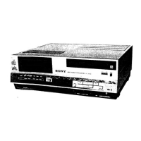
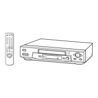
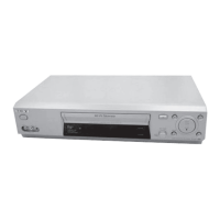
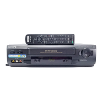
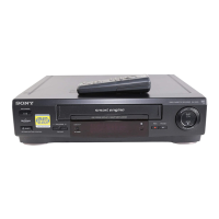
Identification and location of front panel buttons, indicators, and inputs/outputs.

Rear Panel Connectors Overview

Identification and location of rear panel connectors and switches.

Mechanical Assemblies

Drum Assembly Components

Diagram showing various parts of the drum mechanism.

Cassette Loading Assembly (1)

Exploded view of the primary cassette loading mechanism parts.

Cassette Loading Assembly (2)

Exploded view of additional parts for the cassette loading assembly.

Function Assembly

Exploded view showing DR boards, solenoids, and related parts.

Tuner/Timer Assembly

Exploded view of the tuner/timer assembly including IF-16 and TP boards.

Tuner/Power Assembly

Exploded view of tuner/power assembly parts including TP-2, TU-23, LF-21, and power transformer.

Drum Assembly

Exploded view detailing the components of the drum assembly.

Chassis Assemblies

Exploded views of various chassis assemblies and their components.

Lower Frame Assembly

Exploded view of the lower frame, including main boards and structural parts.

Remote Control Unit Exploded View

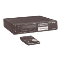
Exploded view of the remote control unit's case, board, and cable.

Circuit Board Diagrams and Locations

Circuit Boards Location Overview

Diagram showing the physical location of various circuit boards within the VCR.

Frame Schematic Diagram

Overall schematic diagram showing interconnections between major circuit boards.

Section 2 Block Diagrams

Overall Block Diagram

A high-level overview of the VCR's main functional blocks and their interconnections.

Video System Block Diagram

Detailed block diagram of the VA-1 board's video processing functions.

Servo System Block Diagram

Block diagrams illustrating the operation of the drum and capstan servo systems.

System Control Block Diagram

Block diagram showing system control logic and motor/solenoid driving circuits.

Audio Circuits Overview

Block diagram of the audio processing section on the VA-1 board.

Timer & Power Supply Block Diagram

Block diagram illustrating the timer and power supply circuits.

Tuner IF Block Diagram

Block diagram of the tuner and IF stages, including board locations.

Timing Charts

Drum Servo Timing Chart

Waveforms and timing sequences for the drum servo system during playback and record.

Capstan Servo Timing Chart (βΙ)

Timing chart for the capstan servo system in Beta I speed mode.

Capstan Servo Timing Chart (βΙΙ)

Timing chart for the capstan servo system in Beta II speed mode.

Capstan Servo Timing Chart (βΙΙΙ)

Timing chart for the capstan servo system in Beta III speed mode.

Tape Speed Automatic Timing Chart (1)

Timing chart illustrating automatic tape speed control for Beta I/II modes.

Tape Speed Automatic Timing Chart (2)

Timing chart illustrating automatic tape speed control for Beta III mode.

System Control Timing Chart

Timing chart illustrating operation modes and signal sequences from the SS-9 board.

Audio Level Diagrams

Audio Level Diagram (Record Mode)

Audio signal level charts for record mode.

Audio Level Diagram (Playback Mode)

Audio signal level charts for playback mode.

Board Schematics and Waveforms

VA-1 Board Waveforms

Waveform examples for various ICs on the VA-1 board during REC/PB operations.

VA-1 Board Schematic Diagram

Detailed schematic of the VA-1 board's signal processing circuits.

RP-5 Board Schematic Diagram

Detailed schematic of the RP-5 board's signal processing circuits.

SS-9 Board Schematic

Schematic and component layout for the SS-9 board controlling servo and system functions.

Board Waveforms and Voltages

Waveforms and voltage readings for various servo/system control boards.

Tuner and IF Section Schematics

Schematic diagrams for the tuner and IF section boards.

Power Supply and Timer Diagrams

Power Supply and Timer Board Mounting Diagrams

Mounting diagrams for power supply and timer related boards.

TP-4 Board Schematic Diagram

Schematic diagram for the TP-4 board, related to timer and power switching.

TP-2 Board Schematic Diagram

Schematic diagram for the TP-2 board, related to the power supply.

LF-21 Board Schematic Diagram

Schematic diagram for the LF-21 board, related to the line filter.

TP-3 Board Schematic Diagram

Schematic diagram for the TP-3 board, related to timer control.

TP-4, TP-6, TP-7 Board Schematic Diagrams

Schematic diagrams for TP-4, TP-6, and TP-7 boards related to timer and power functions.

Section 4 Exploded Views

Front Assembly Exploded View

Exploded view of the front panel components and assembly.

Cabinet Assembly Exploded View

Exploded view showing the main chassis, lid, and bottom plate components.

Section 5 Electrical Parts List

VA-1 Board Component List

List of components for the VA-1 board, including capacitors and resistors.

VA-1 Board Component List (Continued)

Continuation of the VA-1 board component list, including resistors and variable resistors.

VA-1 Board Component List (Resistors, Transistors)

Further listing of VA-1 board components, including resistors, transistors, coils, and diodes.

VA-1 Board Component List (Resistors)

Comprehensive list of resistors for the VA-1 board.

VA-1 Board Component List (Resistors - Continued)

Continuation of the VA-1 board resistor list.

VA-1 Board Component List (Resistors - Final)

Final part of the VA-1 board resistor list.

VA-1 and RP-5 Board Component Lists

Component list for VA-1 board (resistors, transformers) and RP-5 board (capacitors).

RP-5 and SS-9 Board Component Lists

Component list for RP-5 board (resistors, transformers, crystal, capacitors) and SS-9 board (capacitors).

SS-9 Board Component List

Component list for SS-9 board, including capacitors, connectors, diodes, and transistors.

SS-9 and DR-1 Board Component Lists

Component list for SS-9 board (diodes, ICs, coils, transistors, resistors) and DR-1 board (diodes, ICs, transistors).

SS-9 Board Component List (Transistors, Resistors)

Continuation of SS-9 board component list, covering transistors and resistors.

SS-9 Board Component List (Resistors)

Further listing of SS-9 board resistors.

SS-9 Board Component List (Resistors - Final)

Final part of the SS-9 board resistor list.

SS-9 and DR-1 Board Component Lists (Continued)

Final component lists for SS-9 board (transistors, resistors) and DR-1 board (capacitors, connectors, diodes, transistors).

DR-1 to DR-7 Board Component Lists

Component lists for DR-1 through DR-7 boards, including transistors, resistors, and switches.

DR-8 to IF-16 Board Component Lists

Component lists for DR-8, DR-9, DR-10, FS-11, FS-12, and IF-16 boards.

IF-16 Board Component List

Component list for the IF-16 board, including transistors and resistors.

IF-16 and TP-2 Board Component Lists

Component list for IF-16 board (transistors, resistors, ICs, coils, neon lamp, volume block) and TP-2 board (capacitors, connectors, diodes, transformer, fuse, IC).

TP-2 to TT-3 Board Component Lists

Component lists for TP-2, TP-3, TP-4, TP-6, TT-5, TT-2, and TT-3 boards.

TT-4 to CP-6 Board Component Lists

Component lists for TT-4, SL-1, FG-2, RM-8, FL-2, TU-23, LF-21, and CP-6 boards.

CP-6 Board Component List

Component list for CP-6 board, including connectors, transistors, resistors, miscellaneous items, and accessories.

Service Manual Corrections

Section 1 General - Page 1-1 General Corrections

Correction notice for the general operating instructions and safety precautions.

Section 3 Printed Wiring Board and Schematic Diagram Corrections

Page 3-9, 3-10 VA-1 Board Corrections

Corrections for the VA-1 board schematic diagrams, showing incorrect vs. correct wiring.

Related product manuals