Do you have a question about the Sony SLV-SE850 and is the answer not in the manual?
Highlights critical components requiring careful replacement.
Outlines post-repair safety verification steps.
Explains how error codes are displayed and their meanings.
Steps for inputting EEPROM data after replacement.
Steps to play back a video cassette tape.
Features like shuttle search, synchronized recording, and timer management.
Performing tape editing tasks and audio dubbing.
Introduction to tape organization and programme recording using SmartFile.
Cross-references problems with relevant manual sections.
Overall system connectivity and signal flow.
Details the video signal processing path.
Illustrates servo and system control interfaces.
Depicts the audio signal path and processing.
Outlines Smart File data management.
Shows power supply distribution and regulation.
Overall schematic overview of the VCR's circuitry.
Detailed schematics for the MA-388 board sections.
Schematics and component layout for the RP-238 bias board.
Schematics and component layout for the FR-169 indicator board.
Schematics and component layout for the DM-95 user function board.
Schematics and component layout for the SE-109 SECAM board.
Component layouts for Smart File and antenna boards.
Schematic diagrams for the ML-21 Smart File board.
Verifying critical voltage levels from the power supply.
Verifying system control signals and clock oscillation.
Adjusting RF and Hi-Fi switching positions for tape output.
Confirming playback video signal and sync AGC levels.
Adjusting Hi-Fi audio system parameters.
| Type | VCR |
|---|---|
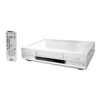
| Brand | Sony |
| Model | SLV-SE850 |
| Video Format | VHS |
| Recording Speed | SP, LP, EP |
| Playback Speeds | SP, LP, EP |
| Tuner | Yes |
| Number of Heads | 4 |
| Hi-Fi Stereo | Yes |
| Remote Control | Yes |
| Clock | Yes |
| Timer Recording | Yes |
| Inputs | Composite |
| Outputs | Composite, RF |