AEP Model
SLV-SE60AE1/SE60AE2
UK Model
SLV-SE70UX/SE80UX
E Model
SLV-SE70EN/SE80EN/SX70EN
French Model
SLV-SE70B/SE80B/SX70B
German Model
SLV-SE70VC1/SE70VC2/SE80VC1/
SE80VC2/SX70VC/SX80VC
Spanish Model
SLV-SE60NP/SE70NP1/SE70NP2/
SE80NP/SX60NP
East European Model
SLV-SE50EE/SE70EE
Greek Model
SLV-SE35EG/SE50EG/SE70EG/SE80EG
Irish Model
SLV-SE70EX
SERVICE MANUAL
VIDEO CASSETTE RECORDER
MICROFILM
S MECHANISM
SLV-SE35/SE50/SE60/SE70/SE80/SX60/SX70/SX80
RMT-V256A/V257B/V259/V259A/V259B/V259C
G
j
Refer to the SERVICE MANUAL of VHS
MECHANICAL ADJUSTMENT
for
MECHANICAL ADJUSTMENTS. (9-921-647-11)
SPECIFICATIONS
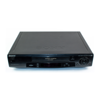
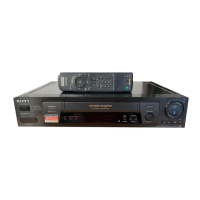
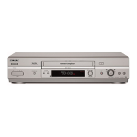
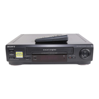
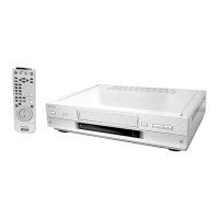
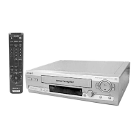
Photo: SLV-SE80
RMT-V259B
System
Channel coverage
B MODEL
SECAM(L)
VHF F2 to F10
UHF F21 to F69
CATV B to Q
HYPER S21 to S41
B/AE1/AE2/NP/NP1/NP2/VC/VC1/VC2
MODEL
PAL(B/G):
VHF E2 to E12
VHF Italian channels A to H
UHF E21 to E69
CATV S01 to S05,S1 to S20
HYPER S21 to S41
EE,EG,EN MODEL
PAL(B/G,D/K)
VHF E2 to E12,R1 to R12
UHF E21 to E69,R21 to R69
CATV S1 to S41,S01 to S05
SE70EX MODEL
PAL (I)
VHFIA to IJ,SA10 to SA13
UHF B21 to B69
CATV S01 to S05,S1 to S20
HYPER S21 to S41
SE70UX/SE80UX MODEL
PAL (I)
UHF B21 to B69(SE70UX)
UHF E21 to E69(SE80UX)
RF output signal
UHF channels 21 to 69
Aerial out
75-ohm asymmetrical aerial socket
Inputs and outputs
LINE-1
(TV)
21-pin
Video input: pin 20
Audio input: pins 2 and 6
Video output: pin 19
Audio output: pins 1 and 3
SE50/SE70EE/EG/EN/SE80/SX70EN/
SX80VC MODEL
LINE-2 IN
VIDEO IN, phono jack (1)
Input signal: 1 Vp-p,
75 ohms, unbalanced,sync negative
AUDIO IN, phono jack (2)(EXCEPT SE50)
AUDIO IN, phono jack (1)(SE50 MODEL)
Input level: 327 mVrms
Input impedance : more than 47 kilohms
EXCEPT AE1/AE2/EE/SE35
LINE-2 IN(SE60NP/SE70B/EX/NP1/NP2/
UX/VC1/VC2/SX70B/VC/SX60)
LINE-3 IN(SE50EG/SE70EG/EN/SE80/
SX70EN/SX80)
21-pin
Video input: pin 20
Audio input: pins 2 and 6
EXCEPT SE35/SE50/SE60/SE70EE/
SE80EG/SX60
AUDIO OUT
Phono jack (2)
Rated output
level: 327 mVrms
Load impedance: 47 kilohms
Output impedance: less than 10 kilohms
SE50EE/SE70EE/SE80EG MODEL
LINE-2 OUT
AUDIO OUT,Phono jack(2)
Rated output level:327mVrms
Load impedance:47 kilohms
Output impedance:less than 10 kilohms
VIDEO OUT,Phono jack(1)
Rated output level:327mVrms
Load impedance:47 kilohms
Output impedance:less than 10 kilohms
General
Power requirements
220 - 240 V AC, 50 Hz
Power consumption
22 W
Operating temperature
5°C to 40°C
Storage temperatur
-20°C to 60°C
Dimensions
EXCEPT SE80B/NP/UX/VC1/VC2/SX80
Approx. 430 x 100 x 314 mm
(Approx. 17 x 4 x 12 3/8inches) (w/h/d)
SE80B/NP/UX/VC1/VC2/SX80 MODEL
Approx. 430 x 100 x 317 mm
(Approx. 17 x 4 x 12 1/2inches) (w/h/d)
including projecting parts and controls
Mass
SE50/SE70EE/EG/EN/SE80/SX70EN/SX80
MODEL
Approx. 4.6 kg
(Approx. 10 lb 2 oz)
EXCEPT SE50/SE70EE/EG/EN/SE80/SX70EN/
SX80
Approx. 4.5 kg
(Approx. 9 lb 15 oz)
Supplied accessories
Remote commander (1)
R6 (size AA) batteries (2)
Aerial cable (1)
EURO-AV cable (1)
AC Plug adaptor(1)
Audio cable(1)
Design and specifications are subject to change
without notice.