EasyManua.ls Logo

Sony SLV-SE45 User Manual

Sony SLV-SE45
75 pages
To Next Page IconTo Next Page
Page #1 background imageLoading...
Page #1 background image
AEP Model
SLV-SE10AE1/SE10AE2
UK Model
SLV-SE20UX/SE30UX/SE45UX
French Model
SLV-SE25B/SE40B
German Model
SLV-SE20VP1/SE20VP2/SE25VC
/SE30VC1/SE30VC2/SE40VC1
/SE40VC2/SE45VC/SX25VC
Spanish Model
SLV-SE25CP/SE30CP/SE40CP/SE45CP
East European Model
Greek Model
SLV-SE10EE/SE10EG/SE30EE/SE40EE/
SE40EG/SX10EG/SX40EG
Irish Model
SLV-SE20EX
SERVICE MANUAL
VIDEO CASSETTE RECORDER
MICROFILM
SLV-SE10/SE20/SE25/SE30/SE40/SE45/SX10/SX25/SX40
RMT-V256/V256A/V257/V257A/V257B/V257C/V259
j
Refer to the SERVICE MANUAL of VHS
MECHANICAL ADJUSTMENT
for
MECHANICAL ADJUSTMENTS. (9-921-647-11)
SPECIFICATIONS
Photo: SLV-SE45
RMT-V259
S MECHANISM
System
Channel coverage(10EE/EG/30EE/40EE/EG/
X10/X40 MODEL)
PAL(B/G,D/K):
VHF E2 to E12,R1 to R12
UHF E21 to E69,R21 to R69
CATV S1 to S41,S01 to S05
PAL(B/G):(10AE1/AE2/40B/25B/45CP/
30CP/VC1/VC2/20VP1/VP2/25CP/VC/40CP/
VC1/VC2/45VC/X25 MODEL)
VHF E2 to E12
VHF Italian channels A to H
UHF E21 to E69
CATV S01 to S05,S1 to S20
HYPER S21 to S41
SECAM(L):(SE25B/40B MODEL)
VHF F2 to F10
UHF F21 to F69
CATV B to Q
HYPER S21 to S41
PAL(B/G):
VHF E2 to E12
VHF Italian channels A to H
UHF E21 to E69
CATV S01 to S05,S1 to S20
HYPER S21 to S41
PAL (I)(20EX/UX MODEL)
VHFIA to IJ,SA10 to SA13(20EX only)
UHF B21 to B69
CATV S01 to S05,S1 to S20(20EX only)
HYPER S21 to S41
PAL (I)(SE30UX/45UX MODEL)
UHF B21 to B69
RF output signal
UHF channels 21 to 69
Aerial out
75-ohm asymmetrical aerial socket
Inputs and outputs
LINE-1
(TV)
21-pin
Video input: pin 20
Audio input: pins 2 and 6
Video output: pin 19
Audio output: pins 1 and 3
LINE-2 IN(10EE/30CP/VC1/VC2/EE/UX/
45CP/UX MODEL)
VIDEO IN, phono jack (1)
Input signal: 1 Vp-p,
75 ohms, unbalanced,sync negative
AUDIO IN,
phono jack (1)
Input level: 327 mVrms
Input impedance : more than 47 kilohms
LINE-2 IN(SE25VC/40VC1 MODEL)
21-pin
Video input: pin 20
Audio input: pins 2 and 6
LINE-2 IN
(25B/CP/VC/UX/40B/CP/VC1/VC2/45VC/
UX/X25 MODEL)
LINE-3 IN
(30CP/VC1/UX/VC2/45CP/UX)
21-pin
Video input: pin 20
Audio input: pins 2 and 6
LINE OUT(10EE/30EE/40EE)
AUDIO OUT,Phono jack(2)
Rated output level:327mVrms
Load impedance:47 kilohms
Output impedance:less than 10 kilohms
VIDEO OUT,Phono jack(1)
Rated output level:327mVrms
Load impedance:47 kilohms
Output impedance:less than 10 kilohms
General
Power requirements
220 - 240 V AC, 50 Hz
Power consumption
22 W
Operating temperature
5°C to 40°C
Storage temperatur
-20°C to 60°C
Dimensions
Approx. 355 x 96 x 285 mm(w/h/d)
including projecting parts and controls
Mass
Approx. 3.8 kg
(Approx. 10 lb 2 oz)
Supplied accessories
Remote commander (1)
R6 (size AA) batteries (2)
Aerial cable (1)
AC Plug adaptor(1)(20EX/UX)
Design and specifications are subject to change without
notice.
w
w
w
.
x
i
a
o
y
u
1
6
3
.
c
o
m
Q
Q
3
7
6
3
1
5
1
5
0
9
9
2
8
9
4
2
9
8
T
E
L
1
3
9
4
2
2
9
6
5
1
3
9
9
2
8
9
4
2
9
8
0
5
1
5
1
3
6
7
3
Q
Q
TEL 13942296513 QQ 376315150 892498299
http://www.xiaoyu163.com

Table of Contents

Question and Answer IconNeed help?

Do you have a question about the Sony SLV-SE45 and is the answer not in the manual?

Sony SLV-SE45 Specifications

General IconGeneral
BrandSony
ModelSLV-SE45
CategoryVCR
LanguageEnglish

Summary

Service Manual Overview and Specifications

System Configurations

Lists channel coverage and system configurations for various models.

Technical Specifications

Details technical specifications including power, temperature, dimensions, and mass.

Safety Precautions and Procedures

Safety-Related Component Warning

Warns about critical components identified by marks that are essential for safe operation.

Safety Check-Out Procedure

Outlines essential safety checks to perform after service before releasing the unit.

Section 1: General Setup

Getting Started: Unpacking and Model Check

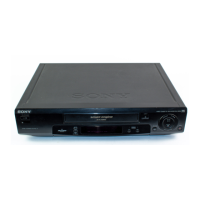
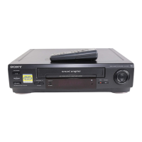
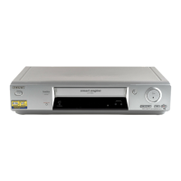
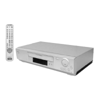
Provides initial steps for unpacking, setting up the remote, and checking the model name.

Setting Up the Remote Commander

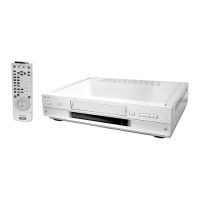
Guides on inserting batteries and using the remote commander for VCR and TV operations.

Initial Setup and Connectivity

Connecting the VCR to Your TV

Explains how to connect the VCR to a TV using EURO-AV or standard antenna connectors.

Auto Set Up Function Guide

Guides on automatically setting TV channels and VCR functions for optimal performance.

Basic Operations and Security

Playing a Tape

Basic steps for inserting a tape and initiating playback.

Setting Your Personal Code

Instructions on setting a personal code for VCR identification and security purposes.

Advanced Recording Features

Recording with VIDEO Plus+ System

Details how to program recordings using VIDEO Plus+ by entering PlusCode numbers.

TV Direct Rec: Recording Current Program

Instructions for recording the currently viewed TV program directly.

Section 2: Disassembly Procedures

Case and Front Panel Assembly Disassembly

Step-by-step instructions for removing the outer casing and front panel assembly.

Accessing FI-15 and DS-83 Boards

Guides on accessing and identifying the FI-15 and DS-83 circuit boards.

Internal Component Identification

Top View of Internal Components

Illustrates the layout and identifies key components visible from the top view of the VCR's interior.

Bottom View of Internal Components

Shows the arrangement and identification of components from the bottom perspective.

Section 3: Block Diagrams

Overall Block Diagram Overview

Presents a high-level overview of the VCR's main functional blocks and their interconnections.

Section 4: Printed Wiring Boards and Schematics

General Notes for PWB and Schematics

Provides common notes and conventions used for printed wiring boards and schematic diagrams.

MA-338 Board Schematics (Part 1)

Detailed schematic for the record/playback circuitry on the MA-338 board.

Section 6: Adjustments

Electrical Adjustments Preparation

Outlines the necessary equipment and setup for performing electrical alignment procedures.

Power Supply Check Procedure

Provides a checklist for verifying critical power supply voltages against specified values.

Section 7: Repair Parts List

Exploded Views and General Notes

Provides general notes on part identification, abbreviations, and safety-critical components.

Front Panel and Upper Case Section Parts

Lists parts and their reference numbers for the front panel and upper casing assembly.

Electrical Parts List (Part 1)

DS-83, FI-15, and MA-338 Board Components

Lists diodes, jacks, resistors, and switches for the DS-83, FI-15, and MA-338 boards.

Power Block and Accessories

Power Block ETXNY165E1D Component List

Lists components for the power block, including capacitors, diodes, ICs, transistors, and accessories.

Related product manuals