EasyManua.ls Logo

Sony SLV-SX717 User Manual

Sony SLV-SX717
86 pages
To Next Page IconTo Next Page
Page #1 background imageLoading...
Page #1 background image
SERVICE MANUAL
French Model
SLV-SE610B/SE710B/SE810B/
SX710B/X9B
German Model
SLV-SE710D/SE810D/SX710D/
SX717D/SX810D/X9D
Italian Model
SLV-SE610A
East European Model
Russian Model
SLV-SE610K/SE610N/SE710K/SE710N/
SE810K/SE810N/SX710K/SX710N/X9N
North European Model
SLV-SE610E/SE710E/SE810E/
SX710E/SX717E/X9E
UK Model
SLV-SE610G/SE710G/
SE710I/SE810G/X9G
VIDEO CASSETTE RECORDER
Refer to the SERVICE MANUAL of VHS MECHANICAL
ADJUSTMENTS VI for MECHANICAL ADJUSTMENTS.
(9-921-647-11)
* The abbreviations of SE610, SE710, SE810, SX710, SX717, SX810 and
X9 contained in this service manual are indicated when these models are
common to all their corresponding models as given below.
RMT-V259/V259B/V259K/V259L/V259R/V259S/V288/V288A/V288B/V288C
SLV-SE610/SE710/SE810/SX710/SX717/SX810/X9
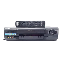
Photo: SLV-SE810
SR MECHANISM
Abbreviated
SE610 SE710 SE810 SX710 SX717 SX810 X9
model name
SE610A SE710B SE810B SX710B SX717D SX810D X9B
All model SE610B SE710D SE810D SX710D SX717E X9D
names SE610E SE710E SE810E SX710E X9E
SE610G SE710G SE810G SX710K X9G
SLV- SE610K SE710I SE810K SX710N X9N
SE610N SE710K SE810N
SE710N
w
w
w
.
x
i
a
o
y
u
1
6
3
.
c
o
m
Q
Q
3
7
6
3
1
5
1
5
0
9
9
2
8
9
4
2
9
8
T
E
L
1
3
9
4
2
2
9
6
5
1
3
9
9
2
8
9
4
2
9
8
0
5
1
5
1
3
6
7
3
Q
Q
TEL 13942296513 QQ 376315150 892498299
http://www.xiaoyu163.com

Table of Contents

Question and Answer IconNeed help?

Do you have a question about the Sony SLV-SX717 and is the answer not in the manual?

Sony SLV-SX717 Specifications

General IconGeneral
BrandSony
ModelSLV-SX717
CategoryVCR
LanguageEnglish

Summary

Section 2 Disassembly

2-1. Upper Case Removal

Procedure for removing the top cover of the VCR unit.

2-3. Power Block (SRV938EK) Removal

Instructions for removing the power supply unit.

2-5. Mechanism Deck Removal

Procedure for removing the VCR's main mechanism deck.

2-6. MA-400 Board Removal

Steps for removing the main control board.

Section 5 Interface, IC Pin Function Description

5-6. Servo/System Control Microprocessor Pin Function (MA-400 BOARD IC162)

Detailed pin function description for the servo/system control microprocessor.

5-7. Mode Control Pin Function (MA-400 BOARD IC420)

Pinout and function description for the mode control IC.

Section 6 Error Codes

6-1. ERROR CODES

List of error codes and their corresponding meanings for troubleshooting.

Section 7 Adjustments

7-1. Mechanical Adjustments

Procedures for performing mechanical adjustments on the VCR.

7-2. Electrical Adjustments

Procedures for performing electrical adjustments and calibration.

Related product manuals