EasyManua.ls Logo

Sony SLV-SX720 User Manual

Sony SLV-SX720
96 pages
To Next Page IconTo Next Page
Page #1 background imageLoading...
Page #1 background image
VDE
vaes
SLV-SE220/SE420/SE620/SE720/
SE727/SE820/SX720/SX72
RMT-V405/V405A/V406/V406A/V406B/V407A/V407B/V407C
SERVICE
MANUAL
AEP
Model
SLV-SE220/SE620/SE720/SE727/
eas
SE820/SX720/SX727
UK
Model
SLV-SE220G/SE720G/SE820
Russian
Model
SLV-SE420K/SE620N/SE720N/
VHS
SE820N/SX720N
o
oO
wo
loelFa
SHOWVIEW’
[ud-4=
Photo
:
SLV-SE620D
(engi
(for
UK
model)
RMT-V406
TS-10
MECHANISM
|
Refer
to
the
SERVICE
MANUAL
of
VHS
MECHANI-
CAL
ADJUSTMENT
MANUAL
VII
for
MECHANICAL
ADJUSTMENTS.
(9-921-790-11)
The
abbreviations
of
SLV-SE220/SE420/SE620/SE720/SE727/SE820/SX720/SX727
contained
in
this
service
manual
are
indicated
when
these
models
are
common
to
all
their
corresponding
models
as
given
below.
Abbreviated
models
name
|SE220__|SE420__|SE620
_|SE720__|SE727_|SE820
_|$X720
AEP
models
SLV-
SE220B
|SE620B
|SE720B
|SE727E
|SE820B
|Sx720D
|$x727D
SE220D
SE620D_|
SE720D
SE820D
|SX720E
SE2201
SE620E
|
SE720E
SE820E
SE7201
UK
models
SLV-
SE220G
-
-
_|SE720G
-
_|SE820G
ae
“fk
Russian
models
SLV-
-
__|SE420K
|SE620N
|
SE720N
-
_|SE820N
|Sx720N
|
-
The
SLV-SE220D/SE620D/SE720D/SX720D/SX727D/SE820D
model
and
SLV-SE420K/SE620N/SE720N/SX720N/SE820N
model
that
have
destination
of
Germany,
Hungary
and
Austria
are
repaired
only
at
the
centralized
service
centers.
Send
these
model
to
the
centralized
service
centers
for
repair.
SPECIFICATIONS
System
LP:
PAL/MESECAM*
Rewind
time
Channel
coverage
11.70
mm/s
Approx.
|
min.
(with
E180
tape)
e
(recording/playback)
ee)
NTSC
16.67
mm/s
Inputs
and
outputs
se
Sane
f
69
(playback
only)
LINE-1
(EURO
AV)
Ra
eau
EP:
NTSC
11.12
mm/s
21-pin
CE
Se
ens
(playback
only)
Video
input:
pin
20
a)
ee
ice
*MESECAM:
for
B
model
Audio
input:
pins
2
and
6
UHF
channels
21-69
Maximum
recording/playback
time
Video
output:
pin
19
issues
10
hrs.
in
LP
mode
(with
E300
tape)
Audho
aut
putapine
Lands
75-ohm
asymmetrical
aerial
socket
2
SGeinied
onan
pase
Tape
speed
ee
VIDEO
CASSETTE
RECORDER
(recording/playback)
NTSC
33.35
mm/s
(playback
only)
SONY.

Table of Contents

Question and Answer IconNeed help?

Do you have a question about the Sony SLV-SX720 and is the answer not in the manual?

Sony SLV-SX720 Specifications

General IconGeneral
BrandSony
ModelSLV-SX720
CategoryVCR
LanguageEnglish

Summary

SPECIFICATIONS

Channel Coverage

Specifies the range of TV channels and CATV frequencies covered by the VCR.

Tape Speed

Lists the different tape speeds (SP, LP, EP) and their usage.

Inputs and Outputs

Details the various input and output connectors and their pin assignments.

General Specifications

Power Requirements and Consumption

Specifies power supply voltage, frequency, and usage in different modes.

Operating and Storage Temperatures

Details the operational and storage temperature ranges for the VCR.

Dimensions and Mass

Provides the physical specifications of the VCR, including size and weight.

Supplied Accessories

Lists the items included with the VCR package.

Safety Information

Component Warning

Alerts users to critical components essential for safe operation.

Safety Check-out Procedure

Outlines checks to perform after service before releasing the unit.

Important Service Guide

Mode Switch Assembly Point

Instructions for aligning the mode switch assembly during installation.

How to Eject Cassette Tape

Procedure to eject a cassette if the unit does not operate normally.

Important Service Guide (continued)

Ejecting Cassette Tape Procedure

Detailed steps for manually ejecting a cassette tape from the VCR.

General Operations

Index to Parts and Controls

Reference to detailed diagrams of VCR components and their locations.

Front Panel Overview

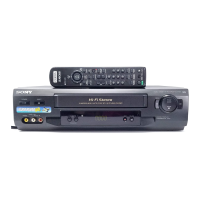
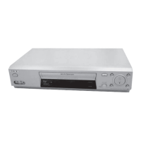
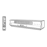
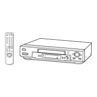
Identifies controls and indicators on the front panel of different models.

Display Window Indicators

Explains the meaning of indicators shown in the VCR display window.

Getting Started

Rear Panel Connections

Illustrates and identifies rear panel input/output connectors for various models.

Remote Commander Overview

Identifies buttons and functions of the remote commander.

Unpacking and Model Identification

Steps for unpacking the VCR and identifying the specific model.

Remote Commander Setup

Inserting Batteries

Instructions for correctly inserting batteries into the remote commander.

Using the Remote Commander

Guidance on operating the VCR and TV using the remote control.

TV Control Functions

Explains how to use the remote to control a TV's basic functions.

Controllable TV Codes

Lists code numbers required for controlling various TV brands.

Controlling Non-Sony TVs

Instructions for setting up the remote to control other TV brands.

VCR Connection and SMARTLINK

TV Connection Scenarios

Explains VCR connection options with and without a Scart connector.

SMARTLINK Features Overview

Introduces SMARTLINK functionality for compatible TVs.

Additional Audio/Video Connections

Describes connecting to stereo systems or external tuners.

Initial VCR Setup

Auto Set Up Function

Guides through automatic setup for language, channels, and clock.

TV System Selection

Procedure to select the appropriate TV system for the area.

Clock, Data, and Language Settings

Setting the VCR Clock

Instructions for setting the time and date, including Auto Clock Set.

Downloading TV Tuner Data

Procedure to transfer preset TV channel data using SMARTLINK.

Changing On-Screen Display Language

How to select the on-screen display language.

Channel and Programme Management

Manual Channel Presetting

Steps to manually set channels if Auto Set Up fails.

Modifying Programme Positions

How to change or disable programme slots and station names.

Channel and Programme Management (continuation)

Disabling Unwanted Channels

Steps to skip unused programme positions when tuning.

Customizing Station Names

How to change or enter station names for programs.

Advanced Recording Features

Canal Plus Decoder Setup

Instructions for connecting and setting up a Canal Plus decoder.

Basic Tape Operations

Steps to insert and play a cassette tape.

Basic Tape Operations (continuation)

Additional Tape Playback Tasks

Common playback operations like stop, pause, fast-forward, and rewind.

Recording TV Programmes

Recording Process Overview

Steps to start and stop recording TV programs.

Checking Remaining Time

How to view the available recording time on the tape.

Watching TV During Recording

How to switch to watch other TV programs while recording.

Recording TV Programmes (continuation)

Saving Recordings

Instructions on how to prevent accidental erasure of tapes.

TV Direct Recording

How to record programs directly from the TV using SMARTLINK.

Dial Timer Recording

Using the Dial Timer

Step-by-step guide to setting timer recordings using the Dial Timer.

Dial Timer Recording (continuation)

Setting the Clock for Dial Timer

How to set the VCR clock for accurate timer functions.

ShowView® System Recording

Preparing for ShowView Recording

Steps to prepare for timer recording using ShowView codes.

ShowView® System Recording (continuation)

Executing ShowView Recordings

Detailed steps for setting up and initiating ShowView recordings.

Auto Tape Speed Function

How the VCR automatically adjusts tape speed for longer recordings.

Timer Recording

Timer Recording Setup

Steps to set up timer recordings, including selecting timer method.

Timer Recording (continuation)

Daily and Weekly Recording Patterns

Options for setting recurring timer recordings.

Using VCR During Timer Recording

Instructions for using the VCR while a timer recording is active.

Playing and Searching at Various Speeds

Playback and Search Operations

Describes various playback modes and search functions.

Using the Shuttle Ring

Instructions for using the shuttle ring for playback control.

Recording Control and Timer Management

Setting Recording Duration Time

How to set the VCR to stop recording automatically after a set time.

Managing Timer Settings

How to check, change, or cancel existing timer recordings.

Stereo and Bilingual Recording

German Stereo System Recording

How the VCR records stereo and bilingual programs.

Selecting Audio Output

How to choose between stereo, bilingual, or mono audio.

NICAM System Recording

NICAM Program Recording

Setup for recording NICAM stereo and bilingual programs.

Sound Recording Methods

Explains how sound is recorded onto video tapes.

Index Function Search

Index Scan Search

How to scan tape for recordings using index signals.

Index Search Operation

Detailed steps for searching specific recordings using index marks.

Picture Adjustment

Adjusting Tape Tracking

Manual tracking adjustment for poor quality recordings.

Picture Sharpness Adjustment

How to use Smart Trilogic for automatic picture sharpness.

Power Saving and Menu Options

Reducing Power Consumption

Steps to minimize power usage by turning off display indicators.

Changing Menu Options

How to navigate and change settings in User Set menus.

Tape Transport System Adjustment

ACE Head Assembly Adjustment Overview

General guide for adjusting the ACE head assembly.

ACE Head Height Adjustment

Detailed procedure for adjusting ACE head height.

ACE Head Tilt Adjustment

Steps to adjust ACE head tilt for tape guide flatness.

Audio Azimuth Adjustment

Procedure to adjust audio azimuth for optimal sound level.

Tape Transport System Adjustment (continuation)

Linearity Adjustment (Guide Rollers)

Procedure to adjust guide rollers S and T for linearity.

RPS to Play Transition Check

Verifies smooth transition from RPS to playback mode.

Reel Torque Specifications

Defines required torque values for reel operation.

Disassembly and Reassembly

Deck Parts Locations Overview

Identifies key parts on the top and bottom views of the deck.

Holder FL Cassette Assembly Removal

Procedure to remove the Holder FL Cassette Assembly.

Disassembly and Reassembly (continuation)

Slider FL Drive and Gear Removal

Steps to remove slider FL drive and gear FL cam.

Lever FL Arm Assembly Removal

Procedure for removing the Lever FL Arm Assembly.

Gear Worm Wheel and Motor Loading Removal

Steps to remove the gear worm wheel and motor loading assembly.

Disassembly and Reassembly (continuation)

Bracket Gear and Gear Joint Removal

Steps to remove bracket gear and gear joints.

Gear Loading Drive Assembly Removal

Procedure to remove gear loading drive, slider cam, and lever assemblies.

Disassembly and Reassembly (continuation)

Gear Loading Drive Assembly Steps

Instructions for assembling gear loading drive, slider cam, and lever assemblies.

Lever Pinch and Tension Drive Removal

Steps to remove the lever pinch drive and lever tension drive.

Disassembly and Reassembly (continuation)

Lever Tension and Band Brake Removal

Steps to remove lever tension and band brake assemblies.

Lever Brake S and T Assembly Removal

Procedure to remove lever brake S and T assemblies.

Disassembly and Reassembly (continuation)

Gear Idle Assembly Removal

Steps to remove the gear idle assembly.

Disk S and T Reel Removal

Procedure to remove the disk S and T reels.

Disassembly and Reassembly (continuation)

Holder Clutch Assembly Removal

Steps to remove the holder clutch assembly.

Lever Up Down and Gear Center Assembly Removal

Procedure to remove lever up down and gear center assemblies.

Disassembly and Reassembly (continuation)

Guide Cassette Door Removal

Steps to remove the guide cassette door.

Lever Unit Pinch Assembly Removal

Procedure to remove lever unit pinch assembly, plate joint, and spring pinch drive.

Disassembly and Reassembly (continuation)

Lever #9 Guide Assembly Removal

Steps to remove the lever #9 guide assembly.

FE Head Removal

Procedure to remove the FE head.

Disassembly and Reassembly (continuation)

ACE Head Removal

Steps to remove the ACE head assembly.

Slider S and T Assembly Removal

Procedure to remove the slider S and T assemblies.

Disassembly and Reassembly (continuation)

Plate Ground Deck and Cylinder Removal

Steps to remove plate ground deck and cylinder assembly.

Belt Pulley and Level Head Cleaner Removal

Procedures to remove belt pulley and level head cleaner assembly.

Disassembly and Reassembly (continuation)

Damper Capstan and Motor Capstan Removal

Steps to remove damper capstan and motor capstan assemblies.

Manual Cassette Ejection Procedure

Detailed steps for manually ejecting a cassette tape.

Maintenance and Lubrication Schedule

Part Maintenance Table

Table detailing cleaning, lubrication, and replacement intervals for parts.

Required Service Tools

List of Tools and Fixtures

Identifies necessary tools and their part numbers for service.

Alignment and Adjustment

Tape Transport System Adjustment Locations

Diagrams showing locations for tape transport system adjustments.

Tape Transport System Adjustment

ACE Head Assembly Adjustment Overview

General guide for adjusting the ACE head assembly.

ACE Head Height Adjustment

Detailed procedure for adjusting ACE head height.

ACE Head Tilt Adjustment

Steps to adjust ACE head tilt for tape guide flatness.

Audio Azimuth Adjustment

Procedure to adjust audio azimuth for optimal sound level.

Tape Transport System Adjustment (continuation)

Linearity Adjustment (Guide Rollers)

Procedure to adjust guide rollers S and T for linearity.

RPS to Play Transition Check

Verifies smooth transition from RPS to playback mode.

Reel Torque Specifications

Defines required torque values for reel operation.

Schematic Diagrams

Main PCB Block Identification

Identifies functional blocks on the main PCB.

Power Supply Schematics

Circuit diagrams for SMPS (A) and (B) and Power sections (A) and (B).

System Control and Servo Schematics

Circuit diagrams for System Control/Servo (A) and (B).

Audio/Video and Hi-Fi Schematics

Circuit diagrams for Audio/Video and Hi-Fi option sections.

Schematic Diagrams (continuation)

Signal Processing Schematics

Circuit diagrams for TM-Block, OSD/VPS/PDC, SECAM, A2/NICAM.

Input/Output and Sub-System Schematics

Circuit diagrams for Input/Output and various sub-systems.

Waveform and Voltage Reference Diagrams

Visual representations of signal waveforms and voltage references.

Schematic Diagrams (continuation)

Audio/Video Detailed Schematic

More detailed circuit diagram for Audio/Video processing.

Hi-Fi Option Detailed Schematic

Detailed circuit diagram for Hi-Fi audio option.

Schematic Diagrams (continuation)

TM-Block Detailed Schematic

Detailed circuit diagram for the TM block.

OSD/VPS/PDC (A) Detailed Schematic

Detailed circuit diagram for OSD/VPS/PDC (A).

Schematic Diagrams (continuation)

OSD/VPS/PDC (A) Detailed Schematic

Detailed circuit diagram for OSD/VPS/PDC (A).

OSD/VPS/PDC (B) Detailed Schematic

Detailed circuit diagram for OSD/VPS/PDC (B).

Schematic Diagrams (continuation)

OSD/VPS/PDC (B) Detailed Schematic

Detailed circuit diagram for OSD/VPS/PDC (B).

SECAM Detailed Schematic

Detailed circuit diagram for SECAM processing.

Schematic Diagrams (continuation)

SECAM Detailed Schematic

Detailed circuit diagram for SECAM processing.

A2/NICAM Detailed Schematic

Detailed circuit diagram for A2/NICAM audio processing.

Schematic Diagrams (continuation)

A2/NICAM Detailed Schematic

Detailed circuit diagram for A2/NICAM audio processing.

Input-Output (2 Scart Jack) Detailed Schematic

Detailed circuit diagram for 2 Scart jack input/output.

Schematic Diagrams (continuation)

Input-Output (2 Scart Jack) Detailed Schematic

Detailed circuit diagram for 2 Scart jack input/output.

Input-Output (1 Scart Jack) Detailed Schematic

Detailed circuit diagram for 1 Scart jack input/output.

Sub-System Schematics

Circuit diagrams for various sub-systems.

Schematic Diagrams (continuation)

Sub-System Schematics

Circuit diagrams for various sub-systems.

Waveform Diagrams

Visual representations of signal waveforms.

Voltage Table

Table listing voltage references for troubleshooting.

Schematic Diagrams (continuation)

Waveform Diagrams

Visual representations of signal waveforms.

Voltage Table

Table listing voltage references for troubleshooting.

Audio/Video Detailed Schematic

More detailed circuit diagram for Audio/Video processing.

Hi-Fi Option Detailed Schematic

Detailed circuit diagram for Hi-Fi audio option.

Schematic Diagrams (continuation)

Audio/Video Detailed Schematic

More detailed circuit diagram for Audio/Video processing.

Hi-Fi Option Detailed Schematic

Detailed circuit diagram for Hi-Fi audio option.

TM-Block Detailed Schematic

Detailed circuit diagram for the TM block.

OSD/VPS/PDC (A) Detailed Schematic

Detailed circuit diagram for OSD/VPS/PDC (A).

Schematic Diagrams (continuation)

TM-Block Detailed Schematic

Detailed circuit diagram for the TM block.

OSD/VPS/PDC (A) Detailed Schematic

Detailed circuit diagram for OSD/VPS/PDC (A).

OSD/VPS/PDC (B) Detailed Schematic

Detailed circuit diagram for OSD/VPS/PDC (B).

Schematic Diagrams (continuation)

OSD/VPS/PDC (B) Detailed Schematic

Detailed circuit diagram for OSD/VPS/PDC (B).

SECAM Detailed Schematic

Detailed circuit diagram for SECAM processing.

Schematic Diagrams (continuation)

SECAM Detailed Schematic

Detailed circuit diagram for SECAM processing.

A2/NICAM Detailed Schematic

Detailed circuit diagram for A2/NICAM audio processing.

Schematic Diagrams (continuation)

A2/NICAM Detailed Schematic

Detailed circuit diagram for A2/NICAM audio processing.

Input-Output (2 Scart Jack) Detailed Schematic

Detailed circuit diagram for 2 Scart jack input/output.

Input-Output (1 Scart Jack) Detailed Schematic

Detailed circuit diagram for 1 Scart jack input/output.

Sub-System Schematics

Circuit diagrams for various sub-systems.

Schematic Diagrams (continuation)

Sub-System Schematics

Circuit diagrams for various sub-systems.

Waveform Diagrams

Visual representations of signal waveforms.

Voltage Table

Table listing voltage references for troubleshooting.

Adjustment Mode Settings

SW7T21 (TEST) Button Location

Identifies the location of the SW7T21 test button for adjustments.

Mechanical Adjustment Test Points

Lists and shows positions of test points for mechanical adjustments.

Mechanical Adjustment Procedures

ACE Head Position (X-Point) Adjustment

Steps to adjust the ACE head position for optimal playback.

Mechanical Adjustment Procedures (continuation)

Head Switching Point Adjustment

Procedure for adjusting the head switching point.

NVRAM Option Setting

How to set NVRAM options after component replacement.

Repair Parts List

Exploded Views Overview

Introduces the exploded views for parts identification.

Mechanical Parts Details

Exploded views of mechanical parts shown from top and bottom.

Electrical Parts List

List of electrical components with part numbers.

Exploded Views (continuation)

Mono Model Instrument Assembly Details

Detailed exploded view and parts list for mono models.

Exploded Views (continuation)

Hi-Fi Model Instrument Assembly Details

Detailed exploded view and parts list for Hi-Fi models.

Exploded Views (continuation)

Mechanical Parts (Top Side) Details

Detailed exploded view of mechanical parts on the top side.

Exploded Views (continuation)

Mechanical Parts (Bottom Side) Details

Detailed exploded view of mechanical parts on the bottom side.

Electrical Parts List (continuation)

Capacitors

List of capacitor part numbers and specifications.

Electrical Parts List (continuation)

Coils and Resistors

Lists part numbers and specifications for coils and resistors.

Semiconductors

Lists part numbers and specifications for semiconductor components.

Electrical Parts List (continuation)

Diodes, ICs, and Connectors

Lists part numbers for diodes, integrated circuits, and connectors.

Electrical Parts List (continuation)

Transistors, Switches, and TM Blocks

Lists part numbers for transistors, switches, and TM blocks.

Varistors and Resistors

Lists part numbers for varistors and various resistors.

Electrical Parts List (continuation)

Resistors

Lists part numbers and specifications for various resistors.

Photo Transistors and Switches

Lists part numbers for photo transistors and switches.

Electrical Parts List (continuation)

Accessories and Vibrators

Lists part numbers for accessories like remote controls and vibrators.

Diodes and Connectors

Lists part numbers for diodes and connectors.

VHS Mechanical Adjustment Manual VII

TS-10 Mechanism Overview

Introduces the TS-10 mechanism for mechanical adjustments.

Disassembly and Reassembly

Deck Parts Locations

Identifies the location of various parts on the deck.

Main Deck Disassembly Steps

Detailed procedures for disassembling the main deck.

Parts Maintenance and Lubrication Schedule

Table for clearing, lubrication, and replacement intervals of parts.

Alignment and Adjustment

Tape Transport System Adjustment Locations

Shows where adjustments are made on the tape transport system.

Tape Transport System Adjustment Procedures

Steps for adjusting the tape transport system.

Disassembly and Reassembly (continuation)

Top View of Deck Parts Locations

Diagram showing the location of parts on the top view of the deck.

Disassembly and Reassembly (continuation)

Bottom View of Deck Parts Locations

Diagram showing the location of parts on the bottom view of the deck.

Disassembly and Reassembly (continuation)

Lever FL Door Removal

Steps to remove the Lever FL Door.

Holder FL Cassette Assembly Removal

Procedure to remove the Holder FL Cassette Assembly.

Disassembly and Reassembly (continuation)

Slider FL Drive and Gear Removal

Steps to remove slider FL drive and gear FL cam.

Lever FL Arm Assembly Removal

Procedure for removing the Lever FL Arm Assembly.

Disassembly and Reassembly (continuation)

Gear Worm Wheel Removal

Steps to remove the gear worm wheel.

Motor Loading Assembly Removal

Procedure to remove the motor loading assembly.

Disassembly and Reassembly (continuation)

Bracket Gear and Gear Joint Removal

Steps to remove bracket gear and gear joints.

Gear Loading Drive Assembly Removal

Procedure to remove gear loading drive, slider cam, and lever assemblies.

Disassembly and Reassembly (continuation)

Gear Loading Drive Assembly Steps

Instructions for assembling gear loading drive, slider cam, and lever assemblies.

Lever Pinch and Tension Drive Removal

Steps to remove the lever pinch drive and lever tension drive.

Disassembly and Reassembly (continuation)

Lever Tension and Band Brake Removal

Steps to remove lever tension and band brake assemblies.

Lever Brake S and T Assembly Removal

Procedure to remove lever brake S and T assemblies.

Disassembly and Reassembly (continuation)

Gear Idle Assembly Removal

Steps to remove the gear idle assembly.

Disk S and T Reel Removal

Procedure to remove the disk S and T reels.

Disassembly and Reassembly (continuation)

Holder Clutch Assembly Removal

Steps to remove the holder clutch assembly.

Lever Up Down and Gear Center Assembly Removal

Procedure to remove lever up down and gear center assemblies.

Disassembly and Reassembly (continuation)

Guide Cassette Door Removal

Steps to remove the guide cassette door.

Lever Unit Pinch Assembly Removal

Procedure to remove lever unit pinch assembly, plate joint, and spring pinch drive.

Disassembly and Reassembly (continuation)

Lever #9 Guide Assembly Removal

Steps to remove the lever #9 guide assembly.

FE Head Removal

Procedure to remove the FE head.

Disassembly and Reassembly (continuation)

ACE Head Removal

Steps to remove the ACE head assembly.

Slider S and T Assembly Removal

Procedure to remove the slider S and T assemblies.

Disassembly and Reassembly (continuation)

Plate Ground Deck and Cylinder Removal

Steps to remove plate ground deck and cylinder assembly.

Belt Pulley and Level Head Cleaner Removal

Procedures to remove belt pulley and level head cleaner assembly.

Disassembly and Reassembly (continuation)

Damper Capstan and Motor Capstan Removal

Steps to remove damper capstan and motor capstan assemblies.

Manual Cassette Ejection Procedure

Detailed steps for manually ejecting a cassette tape.

Maintenance and Lubrication Schedule

Part Maintenance Table

Table detailing cleaning, lubrication, and replacement intervals for parts.

Required Service Tools

List of Tools and Fixtures

Identifies necessary tools and their part numbers for service.

Alignment and Adjustment

Tape Transport System Adjustment Locations

Diagrams showing locations for tape transport system adjustments.

Tape Transport System Adjustment

ACE Head Assembly Adjustment Overview

General guide for adjusting the ACE head assembly.

ACE Head Height Adjustment

Detailed procedure for adjusting ACE head height.

ACE Head Tilt Adjustment

Steps to adjust ACE head tilt for tape guide flatness.

Audio Azimuth Adjustment

Procedure to adjust audio azimuth for optimal sound level.

Tape Transport System Adjustment (continuation)

Linearity Adjustment (Guide Rollers)

Procedure to adjust guide rollers S and T for linearity.

RPS to Play Transition Check

Verifies smooth transition from RPS to playback mode.

Reel Torque Specifications

Defines required torque values for reel operation.

Related product manuals